The Flickr Artistsdepiction Image Generatr

About

This page simply reformats the Flickr public Atom feed for purposes of finding inspiration through random exploration. These images are not being copied or stored in any way by this website, nor are any links to them or any metadata about them. All images are © their owners unless otherwise specified.

This site is a busybee project and is supported by the generosity of viewers like you.

Mercury/Northrop N-227 capsule (Tony Chong Blog website download) by Mike Acs

© Mike Acs, all rights reserved.

Mercury/Northrop N-227 capsule (Tony Chong Blog website download)

Downloaded, edited & uploaded by me because it’s rare, looks cool, is enlightening/informative and sheds a little more light on the enigmatic artist “Todd”…in the process confirming my assumption of him/her being a Northrop Corporation artist.
Doing my insignificant part in preserving “space” history, primarily the imagery, and its rich (to me) legacy.
And, not to mention, a WIN.

Based on the general appearance of the capsule, that of Big Joe 1, I'm assuming this work to be ca. 1959.

And I love the Piasecki (Vertol) H-21 helicopter moving in. Piasecki...who knew...did you?!? I didn't.

ghostmodeler.blogspot.com/2012/10/chasing-mercury-northro...
Credit: Tony Chong’s blogspot website

Thank you, Mr. Chong!

www.secretprojects.co.uk/threads/mercury-capsule-contract...
Credit: SECRET PROJECTS FORUM website

STS01_v_c_o_TPMBK (unnumbered, 82-H-300 eq, 82-HC-288 eq) by Mike Acs

© Mike Acs, all rights reserved.

STS01_v_c_o_TPMBK (unnumbered, 82-H-300 eq, 82-HC-288 eq)

“Space Art - “Columbia Launch Fantasy,” Mixed media painting by artist Andreas Nottebohm is his interpretation of the first launch of the Space Shuttle Columbia, April 12, 1981, Kennedy Space Center.
(NASA Art Program)”

Above per the verso caption of a numbered version.

x.com/PoliticsAndEd/status/1579206130659909632
Credit: Politics & Education/X

cranchedfornow.blogspot.com/2008/01/art-from-space-world-...

Specifically...possibly a variant:

blogger.googleusercontent.com/img/b/R29vZ2xl/AVvXsEh9kpjg...
Both above credit: "Cranched For Now" website


The artist’s website, which no longer seems to be maintained/updated:

andreasnottebohm.net/home/
Credit: Andreas Nottebohm’s website

Most disappointingly, the NASA tab yields this:

andreasnottebohm.net/nasa-2/

Also:

www.andrewweissgallery.com/collections/andreas-nottebohm?...
Credit: “Andrew Weiss Gallery” website

Interesting, from 2003:

"San Rafael artist Andreas Nottebohm's "Columbia Launch Fantasy," painted in 1981, is the first work visitors encounter in the art gallery at the Kennedy Space Center. The work was created as part of NASA's Copernica project, in which artists were commissioned by the space agency to create works focusing on aspects of the space program. Nottebohm also created a work about the first night launch of Columbia and others based on research at Ames Research Center and Voyager 2's trip to Neptune. He also designed NASA's 25th anniversary poster."

At/From:

www.sfgate.com/entertainment/article/the-art-of-columbia-...
Credit: SFGATE website

"Copernica project" = NASA Art Program??? Whatever it is, it's a first-heard for me. And...25th anniversary "poster". Hmmm. Is it the following??? I'm dubious:

static.wikia.nocookie.net/logopedia/images/d/dd/NASA_25_%...
Credit: Fandom/Logopedia website

I'm dubious.

Lastly:

www.nasa.gov/history/history-publications-and-resources/n...

Specifically:

www.nasa.gov/wp-content/uploads/2023/04/sp-4407-etuv4.pdf...

STSprog-fut_v_c_o_TPMBK (S-74-16198, 108-KSC-74PC-93 eq) by Mike Acs

© Mike Acs, all rights reserved.

STSprog-fut_v_c_o_TPMBK (S-74-16198, 108-KSC-74PC-93 eq)

"Artist Concept Shuttle Liftoff"

Above per the black and white version.

One of several variations, by talented North American Rockwell/Rockwell International artist Manuel E. Alvarez.

X-15 release, with ext. tanks & ramjet ('AIRTEAMIMAGES.com' website download) by Mike Acs

© Mike Acs, all rights reserved.

X-15 release, with ext. tanks & ramjet ('AIRTEAMIMAGES.com' website download)

Beautiful ca. 1963/64 color artist’s concept depicting the release of X-15A2 from its B-52 mothership. Note the scramjet & one of the two external fuel tanks.
Per Google’s AI Overview:

“While there were plans to incorporate a scramjet, it was never actually used in flight. The fuselage was extended to accommodate liquid hydrogen for a planned scramjet, but the scramjet itself was only flown in mockup form and never tested during X-15 flights. Wikipedia states that the dummy scramjet was mounted on the ventral fin of the X-15A-2 and was damaged during landing due to heat, breaking off and falling away.”

I assume, maybe, that this work is also by D. E. Wilson, as was the original (without scramjet & external tank(s)), which I’ve linked to below.

I downloaded the image from the following website. In doing so, I cropped out their bullshit copyright claim, as I don’t recognize it. They should be thankful I’ve provided some free, albeit insignificant, publicity:

www.airteamimages.com/north-american-x-15_56-6671_usa-us-...
Credit: “AirTeamImages” website

fut_v_bw_o_n (ca. 1959, Martin Co. photo no. 8P-63919) by Mike Acs

© Mike Acs, all rights reserved.

fut_v_bw_o_n (ca. 1959, Martin Co. photo no. 8P-63919)

“MOON BASE -- As a solar system satellite vehicle proceeds en route to another planet (top), a lunar transfer vehicle with wheeled base and reversible-thrust power plants prepares to land at a moon base. Personnel are housed in spherical chamber capped by parabolic antenna. Hydroponic farms are shown on moon base beneath transparent circular domes.”

Dated by Mr. Stanilla as having been completed August 1959. Interestingly, it’s missing the “STOIKO-CROSS” reference that commonly accompanied his signature. So, possibly, this was prior to/after(?) his affiliation with them?
And…although of course commensurate with the time period - so I guess, to be expected - I just love the look of his works. They’re so aesthetically appealing…and the detail…feasibility & practicality be damned. Enjoy.

The fold/crease line in the upper left white border is tenuously keeping the corner attached. Prior to me, it was probably folded for 65+ years, likely under some weight for extended periods of time.

I’ve never previously seen this work by him. Note the solar glare/radiance extending up from beyond the lunar horizon…nice dramatic touch. And “solar system satellite vehicle”…I love it.

x.com/marco_nerli/status/684992825113579520
Credit: Nerli Ballati Marco/X

g (g08)_v_bw_o_n (66-H-272, S66-24416, 104-KSC-66-4455) by Mike Acs

© Mike Acs, all rights reserved.

g (g08)_v_bw_o_n (66-H-272, S66-24416, 104-KSC-66-4455)

“1965 WAS THE YEAR OF GEMINI!”

“Artist sketch of the Gemini-8 Astronauts, Neil A. Armstrong, command pilot, and David R. Scott, pilot, watching an engineer at work on the Titan II, Pad 19. The Gemini-8 crew for the National Aeronautics and Space Administration’s three day mission will attempt to achieve the first rendezvous and docking of two spacecraft in earth orbit.

Art by George Mathis,
Aerojet-General Corp.”

A rare acknowledgement of an artist (other than Robert McCall) in a (contractor originated) NASA-issued photo. I wonder how Aerojet-General swung that? Granted, Mr. Mathis was very talented, but so were many “anonymous” others. I'll take it.
Another work that appears to be in chalk or charcoal pencil.

Note the Aerojet-General logo - a capital letter “G” (minus text) - on each thrust chamber.

fut_v_bw_o_n (ca. 1961/62, Ryan Aeronautical photo no. 62133) by Mike Acs

© Mike Acs, all rights reserved.

fut_v_bw_o_n (ca. 1961/62, Ryan Aeronautical photo no. 62133)

“Illustration of an aerospace vehicle which incorporates an aero-electric propulsion system features circular disk configuration.”

The above, and all following, taken from “Ryan Reporter”, VOL. 23, FEB., 1962, NO. 1:

“ELECTRICITY for SPACE EXPLORATION

"I have produced electrical discharges the actual path of which, from end to end, was probably more than one hundred feet long; but it would not be difficult to reach
lengths one hundred times as great.
"I have produced electrical movements occurring at the rate of approximately 100,000 horsepower, but rates of 1-, 5- or 10,000,000 horsepower are easily practicable.
"Instead of sending sound-vibrations toward a distant wall, I have sent electrical vibrations toward the remote boundaries of the earth, and instead of the wall the earth has replied. In place of an echo I have obtained a stationary electrical wave, a wave reflected from afar.
"My measurements and calculations have shown that it is perfectly practicable to produce on our globe, by the use of these principles, an electric movement of such magnitude that, without the slightest doubt, its effect will be perceptible on some of our nearer planets, as Venus and Mars. In fact, that we can produce a distinct effect on one of these planets in this novel manner, namely, by disturbing the electrical condition of the earth, is beyond
any doubt.

"We are whirling through endless space with an inconceivable speed, all around us everything is spinning, everything is moving, everywhere is energy. There must be some way of availing ourselves of this energy more directly. Then, with the light obtained from the medium, with the power derived from it, with every form of energy obtained without effort, from the store forever inexhaustible, humanity will advance with giant strides. The mere contemplation of these magnificent possibilities expands our minds, strengthens our hopes and fills our hearts with supreme delight."

Nikola Tesla – 1895


TESLA was an electrical genius whose scientific discoveries and inventions were basic to modern electrical and electronic engineering. He also discovered and demonstrated the principles of high frequency, high potential currents shown in the historic photograph on the preceding page. These were the famous Colorado Springs experiments. The electromagnetic fields created were so intense that they perceptibly affected the distribution of the electrical potential of the earth. In Tesla's words, "In these experiments, effects were developed incomparably greater than any ever produced by human agencies, and yet these results are but an embryo of what is to be."
Such a force field can be applied widely, including electric aerospace propulsion. Within the next ten years electric propulsion will play a leading role in making extensive space trips possible. This conclusion has been ex- pressed in recent years by many researchers. They have compared the advantages and limitations of various space propulsion methods.
Chemical propulsion is the only presently available means for attainment of orbital speeds and altitudes. This is its chief value. Multimillion pound chemical super- boosters can put significant payloads into interplanetary orbits for manned expeditions to the moon, and possibly Venus and Mars. The estimated cost of these projects is staggering. In addition, the exploration of our nearest planets requires transit times of one to three years for a round trip planned on the capability of chemical propulsion. This aspect alone is sufficient to make electric propulsion a highly advantageous method of fuel conservation. For trips beyond Mars, electric propulsion is mandatory both to conserve fuel and also to shorten transit time. Chemical systems would require years or even decades for a round trip. Electrically propelled space vehicles have great payload capability. A Martian round trip, for example, has a payload ratio of almost 50 per cent. This means that these electric vehicles will offer comfortable living space for "shirt-sleeve" environment and adequate power for utilities.
Most electric propulsion systems are very small thrust devices. This limits them to missions beyond the atmosphere of the earth. Because of this, it is believed that this shortcoming is in the nature of electric propulsion. Consequently, it appears that orbit injection can only be accomplished by chemical means, and by chemo-nuclear means in the future. Once the orbit is established, the electric system would take over in providing thrust.
There are very severe problems in maneuvering spacecraft. For example, the spacecraft may require a radically changing course, should an unexpected emergency occur during any point of trajectory.
Such maneuverability is absolutely necessary for practical space systems of the future which have progressed beyond the development stage of present rockets. Both the injection into orbit and practical maneuverability in space demand high thrust propulsion and fuel economy simultaneously. A possibility of meeting these requirements is electro-chemical propulsion. Here, chemical fuels provide a slight exhaust mass which is accelerated by ultra high electromagnetic fields. The prime source of vehicle energy, capable of producing the extremely high force fields, must not require chemical fuels for its own operation. This requires nuclear energy sources or some practical system of converting radiation energy pervading space. In either case, the vehicle size is certain to be large to accommodate the primary energy source. Its weight must not exceed a reasonable fraction of the vehicle's gross weight. Spaciousness is required for physiological and psychological comfort of the crew as well as to increase the safety against meteorite hazards by an interlock escape system. Most approaches involve the study of assembling large structures in space by combining rendezvous techniques with payload capability of large chemical boosters. However, there are severe problems of weightlessness, inertial forces of large parts floating in space, gyroscopic and tidal forces warping large space structures in various stages of assembly, and hazards to men working in free space.
An alternative to this approach of assembling large vehicles in space is being investigated at Ryan as a part of an Electric Aerospace Propulsion concept based on the following:
A completely assembled, large aerospace vehicle should be capable of performing throughout the altitude range, from hovering at sea level to the attainment of orbital speeds, in such a manner as to include the performance characteristics of a helicopter, a propeller aircraft, a jet airplane, a ramjet and a space vehicle into an integrated system design.
Theoretical investigations based on this premise and supported by an initial experimental program have indicated a possible solution to this objective. The key is contained in the afore- mentioned concept of electro-chemical propulsion, enlarged by the concept of an electric air breathing engine. Efficiency requires that the velocity of the exhaust jet should be matched to the vehicle velocity. At low speeds the jet velocity should be small. As vehicle speed is increased, so also should the jet velocity be increased to maintain high efficiency of energy conversion. However, using small jet velocities for take-off requires a large exhaust mass, as in the case of a helicopter whose rotor causes a large air mass to move with relatively small downwash velocity. At the somewhat higher speeds developed by subsonic aircraft, the rotor of a helicopter is replaced by a propeller which moves a smaller air mass at higher speeds. At the supersonic velocities of a jet airplane, the flow of exhaust mass is still smaller but its velocity is further increased.
With an electric air breathing engine this can be achieved by force field control, capable of moving large air masses at low speeds and smaller air masses at higher velocities. A number of vehicle geometries are suitable for satisfying the requirement of velocity and mass control of the exhaust jet. One such geometry, offering additional design advantages of minimum structural weight, large volume and cargo capacity combined with desirable aerothermodynamic characteristics, is shown in the illustration as a circular disk vehicle. This geometry is also particularly suitable for hovering close to ground, because the annular jet augments very substantially the cushion effect of the air trapped between the vehicle and the ground.
By these principles, the efficiency and the thrust of electric aerospace propulsion can be maintained at high levels throughout the entire velocity and altitude range. After leaving the atmosphere, electric propulsion consists of a combination of intense force fields accelerating colloidal chemical plasma; the heavier elements being
used for high thrust performance and lighter elements for sustained vehicle acceleration.
Research is continuing in the area of generation and control of high electro- magnetic field intensities and colloidal plasma combined with the principle of an electric air breathing engine. Aeroelectric propulsion is expected to be a practicable and valuable method for powering aerospace vehicles.”

At/from the wonderful Internet Archive website:

ia800700.us.archive.org/2/items/ryanreporter231263ryan/ry...

Very nice artwork by Ryan Aeronautical staff artist Matt Giacalone.

g_v_bw_o_n (66-H-983) by Mike Acs

© Mike Acs, all rights reserved.

g_v_bw_o_n (66-H-983)

“Artist’s conception of the rendezvous and docking maneuver in space when the two-man National Aeronautics and Space Administration Gemini spacecraft mates with the Agena Target Vehicle. Textron’s Bell Aerosystems Company builds the 16,000-pound thrust Agena liquid rocket engine for the target vehicle (at right) as well as a twin-module secondary propulsion system which fits snugly astride the Agena’s aft rack. The secondary propulsion system orients the propellant in the tanks of the Agena vehicle and adjusts its orbit.”

Secondary propulsion system? Who knew? Did you?? I didn’t!!!

“Mated”? Was the caption writer not familiar with “docked”? Ugh.

Interesting:

www.nasa.gov/history/SP-4002/p2b.htm

Specifically:

www.nasa.gov/wp-content/uploads/static/history/SP-4002/im...

I’ve never seen this at such an amazing resolution.

digitalsc.lib.vt.edu/Ms1989-029/Ms1989-029_B06_F1b_Photo_...
Credit: Virginia Tech Special Collections and University Archives website

a_v_c_o_AKP (ca. 1965-67, unnumbered ctr/NASA photo) by Mike Acs

© Mike Acs, all rights reserved.

a_v_c_o_AKP (ca. 1965-67, unnumbered ctr/NASA photo)

“LEM LUNAR LIFT-OFF”

A wonderful ca. 1966/67 artist’s concept I’ve never seen, by an artist – R. Ward (I think) – I’ve never heard of.

It looks like a LEM M-3/M-5 transitional/“hybrid” to me, with the distinctive curved/rounded (with some faceted) exterior panels, but with a squared forward egress/ingress hatch. Note also the jagged lunar surface features, common in earlier artist’s concepts. So, it’s possible, as was the case with other LEM/LM artist’s concepts, that this is a subsequent variation in which only the forward hatch was updated. The RCS engines are firing as well, I think also indicative of an earlier ‘base’ rendering.
Finally...oddly…the ascent stage appears to be left-to-right reversed, confirmed by the S-Band Steerable Antenna being on the wrong side. However, the signature is readable, so the image itself is correctly oriented. Hmm. ¯\_(ツ)_/¯

Maybe THE Mr. Ward? If so, another WIN:

www.hydepark.thomasfuneralhomes.com/obituary/Robert-Ward
Credit: Carroll-Thomas Funeral Home website

STSprog/fut_v_c_o_TPMBK (1975/76, Thiokol Corp. photo, neg. no. 55979-1, 108-KSC-76PC-147 eq) by Mike Acs

© Mike Acs, all rights reserved.

STSprog/fut_v_c_o_TPMBK (1975/76, Thiokol Corp. photo, neg. no. 55979-1, 108-KSC-76PC-147 eq)

“A dramatic moment during the flight of the Space Shuttle will be when the solid rocket boosters separate from the Shuttle at an altitude of 26 miles. The two booster motors have supplied 5,200,000 pounds of thrust during the first two minutes after launch. Nearly 150 feet long and 12 feet in diameter, the massive boosters will tumble majestically earthward until parachutes open to slow their fall. After they splash into the ocean, ships will retrieve the boosters. Disassembled, the rocket motors will be shipped back to Utah, where Thiokol will refurbish and reload the motors with solid propellant, and then return them to the launch site for yet another flight.”

A rare surviving Thiokol depiction of their product. I can see a lot of Thiokol’s SRB promotional images being shelved & discarded after STS-51L…and rightfully so. A striking depiction nonetheless, especially with the orbiter, other than the SSME exhaust plumes, being darkened, thus highlighting the SRBs & ET. I’m also liking the brushed steel look of the orbiter.

On the verso of the NASA appropriated (108-KSC-76PC-147) version of the photograph:

"Boosters, using Thiokol solid rocket motors, eject from space shuttle at conclusion of launch phase."

Eject. Really…”eject”…REALLY??? GOOD GRIEF.

Last but not least, thanks to “Space World” magazine, specifically, Volume. N-12-168, December 1977, with the image being featured on the cover, in color, the artist is identified as Morton-Thiokol’s Donald Osborne, i.e. a WIN.

fut/Marsexp_v_c_o_KPP (S94-26681) by Mike Acs

© Mike Acs, all rights reserved.

fut/Marsexp_v_c_o_KPP (S94-26681)

"HARD SCIENCE ART CONCEPT --- (Artist's concept of possible exploration programs.) Two kilometers above the lava flows of Mars' Tharsis Bulge region, a geologist collects stratigraphy samples from the eastern cliff face at the base of Olympus Mons, the solar system's largest known shield volcano. To better understand the geologic evolution of the Arizona-sized volcano, the scientist investigates the layers of hardened lava that make up the massive feature. The block-like nature of the rock face, caused by columnar jointing, is similar to features on Earth, such as Wyoming's Devil's Tower. Human exploration of Mars will provide tremendous insight into the origin and evolution of our planetary neighbor while simultaneously addressing similar questions about our own planet. Such exploration challenges will place unprecedented demands on our Extravehicular Activity (EVA) systems as we seek to routinely operate in remote and hostile environments. These images produced for NASA by Pat Rawlings. Technical concepts from NASA's Planetary Projects Office, Johnson Space Center (JSC)."

Yet another exquisite work by Mr. Rawlings, so it really doesn't get much better. Take in the detail...of everything...from the clouds to the Astronaut's carabiner, and EVERYTHING in-between. Amazing.

www.humanmars.net/search/label/Pat%20Rawlings?m=1
Credit: humanMars.net website

Although not to be found at the following, enjoy those that are:

www.patrawlings.com/art-gallery/mars
Credit: Pat Rawlings

fut/TtnLdr_v_c_o_TPMBK (ca. 1976, JPL photo no. P-16927) by Mike Acs

© Mike Acs, all rights reserved.

fut/TtnLdr_v_c_o_TPMBK (ca. 1976, JPL photo no. P-16927)

"TITAN LANDER"

And the rest is what’s on the verso of the black & white version of the photo, along with what I dug up when I posted it in 2020.


"Saturn has a remarkable earth-like moon named Titan, which has a heavy atmosphere. Scientists would like to land a Viking-type package there in the late 1980s."

A beautiful & dynamic depiction by JPL artist Ken Hodges.

Possibly/Apparently part of JPL’s “Purple Pigeon” effort.

Epilog:

Pathetically, as has been the case with many other formerly semi-useful & moderately informative NASA sites, particularly those that hosted imagery/photos, JPL head-shed would appear to have quaffed the Koolaid as well.
The following is what's still available, as of 21 March 2024 at the following site, which is "No Longer Maintained". As such, also no longer with an image that was a probable companion to mine:

www.jpl.nasa.gov/blog/tag/ken-hodges/

“Titan Saturn Mission Artwork, 1976
By Julie Cooper

In the 1970s and 80s, before advanced computer graphics, artist Ken Hodges was hired by JPL to create paintings that depicted many different missions – some in the planning stages and some only imagined.

Bruce Murray became JPL's Director in 1976, and he advocated new missions (Purple Pigeons) that would have enough pizzazz to attract public and scientific support. Hodges painted many of the Purple Pigeon images, including this scene of a Saturn orbiter with a lander going to the surface of Saturn's largest moon Titan. This artwork was done almost 30 years before Cassini's Huygens Probe reached the surface of Titan. Cassini was launched in 1997 and spent seven years traveling to Saturn. The probe was released in December 2004, and landed on Titan on January 14, 2005.

For more information about the history of JPL, contact the JPL Archives for assistance. [Archival and other sources: P-numbered photo albums and indexes, Cassini and Huygens web pages.]

Julie Cooper

ABOUT THE AUTHOR
Julie Cooper, Certified Archivist

Julie Cooper is a certified archivist who identifies and processes collections for the JPL Archives, and helps researchers find information about the history of JPL.”

Buh-bye. Ain't that right NAssA...and now, JPL…whoevers?
Sad, disappointing & pathetic...as has become the norm for photographic documentation, archiving & preservation…at least WRT what’s available/presented to the public, i.e. the taxpayers.

STSprog/fut_v_c_o_AKP (ca. 1970/71, MDAC photo no. POGP 316-870) by Mike Acs

© Mike Acs, all rights reserved.

STSprog/fut_v_c_o_AKP (ca. 1970/71, MDAC photo no. POGP 316-870)

Very nice ca. 1970/71 overhead view of a Phase-B McDonnell Douglas Astronautics Company (MDAC) shuttle in orbit.

Damned if I could find any matches for this design. No central vertical stabilizer, instead with “them” at the wingtips. Are they still referred to as vertical stabilizers out there? Are they instead winglets? Or are they too big to be referred to as winglets? And because of this appearance, it has a “baseline” NASA-designed orbiter look to it, from ca. 1969…I think. Being a MDAC 'consortium' entry, it also looks like a Spacemaster derivative/evolution. Further confusion (for me) was what appears to be a single main engine, which was never the case for any orbiter design, ever…to my knowledge. Despite the perspective, the second one should’ve still been at least marginally visible/depicted IMHO.

Finally, note the dual/double-decker/two-for-one communications(?) satellite deployment configuration, them being attached to a…what…space tug/Orbital Transfer Vehicle? If so, it should be reusable, right. Is it? And look how wide it is, with the way the propellant(?) tanks are mounted to the “bus”. Does this sort of confirm this hangs out in orbit, waiting to be employed, as is apparently the case here. Can the tanks be jettisoned, in order to be positioned/stowed in the payload bay, say for repairs or refurbishment. I doubt it would be secured transversely, with all tanks still attached.
And then there’s the payload still in the payload bay, with what appear to be the same type/size of tanks, but, mounted to the end of its bus, instead of ringing it, as in the deployed stack.
Further fuel for the murky, amorphous, dynamic, and confusing (to me) Phase-A —> Phase-B shuttle thing.

Oh yeah, one more…check out the 1950’s ray-gun looking gizmo deployed at the back corner of the payload bay. Rendezvous radar? Communications antenna?

A similar double satellite deployment scenario is linked to below.

a_v_c_o_AKP (unnumbered NAA & NASA photo no. 63-Apollo-128 eq) by Mike Acs

© Mike Acs, all rights reserved.

a_v_c_o_AKP (unnumbered NAA & NASA photo no. 63-Apollo-128 eq)

"One astronaut will always be fully suited in space attire for emergency."

Above per the numbered black & white version, linked to below.

One of many gorgeous images in this 1963-series of NAA/NASA works by Gary Meyer.

I've never seen this in color prior to this. In wonderful condition, with ample gloss.

Note the identical rotational(?) hand controllers…on what appears to be the LMP’s couch. Huh? But hey, it’s only 1963, so all is forgiven. 😉 And it’s Gary Meyer!

MISS_v_bw_o_n (ca. 1958, unnumbered General Electric/USAF photo) by Mike Acs

© Mike Acs, all rights reserved.

MISS_v_bw_o_n (ca. 1958, unnumbered General Electric/USAF photo)

“In the spring of 1958, after President Dwight Eisenhower called to create a civilian space agency, the US Air Force assumed it would lead any national spaceflight effort. As such, the service prepared a detailed, multi-stage plan called Man in Space with the goal of landing a man on the Moon by the mid-1960s.

The first phase of the Man in Space program was a technical demonstration phase called Man in Space Soonest (MISS). This phase would take the first steps in space to understand the human factors involved. The first six flights would be robotic missions designed to test the hardware and flight systems, followed by six animal flights over six months to test the live support system. Once everything was proven, a man would launch, ideally as early as October of 1960. These manned flights would round out the technical needs for the MISS phase by developing reentry and recovery techniques.

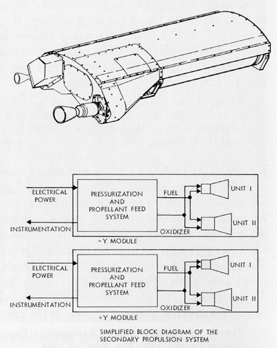
As though to compliment the simple goals of the MISS phase, the spacecraft for all stages was very basic. It was expected to be a simple high-drag, zero-lift, blunt-nosed cylinder eight feet in diameter with a flared bottom and an ablative heat shield to protect the passenger from the heat of reentry. The flared skirt would house the reaction control jets for in-orbit attitude control, the retrorockets that would start the spacecraft on its reentry path to Earth, and the recovery parachutes for a splashdown at sea. Throughout the mission, the pilot would lie on his back on a couch, and though it would be pressurized he would still wear a pressure suit as an extra safety measure. Alongside the pilot would be a certain amount of instrumentation, including the main guidance and control systems as well as the secondary power pack, telemetry and voice communications system.

MISS was intended to solve the key unknowns of human spaceflight, keeping the man out of the loop for his own safety; no one wanted to risk a human pilot in case it turned out that weightlessness was debilitatingly disorienting. The pilot would have increased control in later flights, but real pilot control wouldn’t come until the second phase of the program, Man in Space Sophisticated (MISSOPH).

Beginning in March of 1961, the first stage of this phase, MISSOPH I, would send robotic and animal flights in larger spacecraft designed to stay aloft for up to two weeks, the average time it would take to fly to the Moon and back. This spacecraft would be more or less a larger version of the MISS spacecraft but with an airlock to facilitate spacewalks. The second stage, MISSOPH II, would take advantage of the larger Super Titan Fluorine booster to launch to extremely high altitudes. The goal would be to get the spacecraft as far as 40,000 miles from the Earth so that when it returned it would reenter the atmosphere at about 35,000 feet per second, roughly the same speed as a spacecraft returning from the Moon. The third stage, MISSOPH III, would be the first to give the pilot a lot of control owing to its radical new shape. Unlike the blunt vehicles before it, MISSOPH III would feature a flat triangular bottom reminiscent of a boost-glide vehicle so the pilot could make smooth, gliding landings on a runway.

The MISSOPH III spacecraft would live beyond its dedicated stage, facilitating both Earth orbital and lunar missions, but not before the third Lunar Reconnaissance (LUREC) phase of the program flew. LUREC was intended to fly simultaneously with the MISSOPH phase beginning April of 1960. The first stage called LUREC I was devoted to figuring out the details of real-time tracking and communications with a spacecraft a quarter of a million miles from home. Once the tracking system was in place, LUREC II missions could launch on flights to test the guidance system that would get a spacecraft to the right target a quarter of a million miles away. Using an array of scientific instruments, these unmanned vehicles would also measure the temperature, radioactivity, and atmospheric density around the Moon, sending back television images at the same time to help mission planners narrow down safe landing sites.

With a better understanding of the lunar environment, LUREC III would be the first stage to attempt a soft landing on the Moon. The spacecraft would use retro-rockets to slow its descent and telescoping legs to cushion the impact. Staying intact was important; having landed, this spacecraft would gather the first in situ data about the Moon’s surface, including seismic and audio data from ground noises.

Building off lessons learned to this point, the final flight phase, Manned Lunar Flight (LUMAN), would be the one to land men on the Moon’s surface. The first stage, LUMAN I, called for circumlunar animal flights as early as May of 1962 to verify the hardware, computer, and life support systems. LUMAN II would fly the same mission but with human pilots on board. LUMAN III would resume unmanned flight, soft landing a payload on the Moon. In the LUMAN IV stage, that same spacecraft would land on, then launch from the Moon’s surface before returning safely to Earth ideally early in 1963.

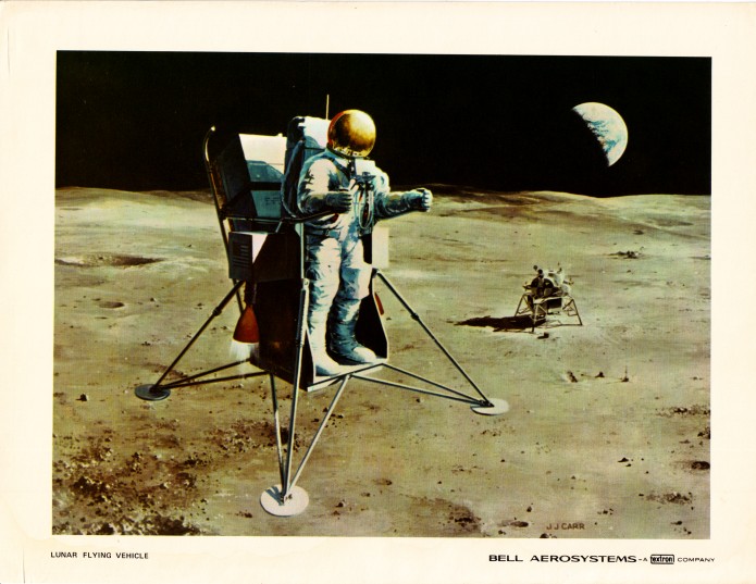
At that point, everything would be in place for a manned lunar landing, the goal of the LUMAN V stage. On this mission, one pilot would bring his spacecraft to a soft landing on the lunar surface. Once there, he would leave the spacecraft through the airlock and, thanks to his special pressure suit, be free to explore the surface. He’d get back into his spacecraft for the return flight home and, upon his return, complete the program’s main goal sometime around 1965. Subsequent missions would focus on larger scientific and military goals; LUMAN VI and LUMAN VII would see more complex landed and orbital missions respectively with far more sophisticated science instruments.

When it was pitched in 1958, this Man in Space program was projected to cost $1.5 billion from the first unmanned missions through to the LUMAN missions. But success hinged on a few things, namely getting priority status and the freedom to take control over whatever resources the Air Force might need to get missions flying as soon as possible. And it needed to get that priority status by July 1, 1958, to stay on schedule; the date was just months after the proposal was written.

Though it pushed improved reconnaissance, communications, and early warning systems for protection against enemy attacks as valuable spinoffs, the Air Force’s proposal was deemed too lofty. It was scaled back to focus on the Man in Space Soonest phase that could be done quickly and before taking on something as challenging as a lunar mission, which suited the service just fine. Besides, there was little question for the Air Force that it would lead the way in space. It looked at the X-15 program as a model, the joint USAF-NACA (National Advisory Committee for Aeronautics) program that had the NACA doing the bulk of the detailed engineering work and the USAF pilots getting the glory of flying record-breaking flights. Why would spaceflight be any different?

Sadly, for the Air Force, President Eisenhower’s decision to found a civilian space agency — NASA — preempted any military program. A year later, NASA’s Mercury program was under development with seven astronauts already selected to fly its missions. The Air Force’s involvement in the program was minimal, supplying Atlas rockets and ground support while the new agency’s astronauts became national heroes.”

Above at/from:

www.popsci.com/how-air-force-planned-to-put-men-on-moon/
Credit: Amy Shira Teitel/Popular Science website


Also:

“It all began on February 15, 1956, in Baltimore, Maryland. Commander of Air Research and Development Command (ARDC) General Thomas S. Power held a staff meeting and called for studies to begin on manned space vehicles that would succeed the joint USAF/NACA X-15 spaceplane program. There were two types of vehicles to choose from: winged and ballistic. One winged approach that would later receive funding was the X-20 Dynamic Soarer. The Task 27544 Manned Ballistic Rocket Research System consisted of a reentry capsule boosted by an intercontinental ballistic missile, or ICBM. Unlike the spaceplane approach, ballistic vehicles could be used for two purposes: speedy delivery of cargo to any point on Earth during an emergency and manned spaceflight.

The Air Force developed a multistage plan with the goal of landing men on the moon by the mid-1960s called Man in Space. Man in Space was split into four phases, the first being MISS. This phase had two objectives: the demonstration of the technological capability and superiority of the United States, and the exploration of the functional capabilities and limitations of the human body in space. Twenty-five flights would have taken place, twelve using the Thor-Vanguard rocket and thirteen using what was referred to as the "Thor-Fluorine". The first six flights would have been robotic missions that tested the spacecraft's hardware and flight systems. The next six would have flown animals over a period of six months to test the life support system and to develop reentry and recovery techniques. They also would have studied the effects of weightlessness and radiation on living creatures. Finally, the first man would fly in space as early as October of 1960. These flights would have used both Thor and Atlas boosters.

Even though the Air Force knew exactly which rockets to use, and therefore already had launch sites picked out as well, one major component was missing— the spacecraft. Even though winged vehicles were still being developed, it was agreed that the optimal choice for MISS was the ballistic reentry capsule. The requirements for such a craft included an ablative heat shield, a window, a 30-inch hatch, and a flared skirt. It also needed to be a high-drag, zero-lift, blunt-nosed cylinder 8 feet in diameter. The flared skirt would contain reaction control jets for attitude control while in orbit, the retrorockets for reentry, and the recovery parachutes that would be deployed during splashdown. Cockpit instrumentation included the main guidance, navigation, and control system, a secondary power pack, and the telemetry and voice communications system. The pilot would lie on his back on a couch during the orbital portion of the mission inside a pressurized cabin. His suit would also be pressurized for safety. According to "Proposal for Man-in-Space (1957-1958)", the astronaut would have been given some control over the spacecraft's attitude and the action of the reentry rockets if he was capable of making decisions during his flight. It was still unknown if microgravity affected cognitive functions.

In June 1958, the first astronaut selection in history took place. Nine pilots were chosen to be the world's first space explorers. Their names were Neil Armstrong, William Bridgeman, Scott Crossfield, Iven Kincheloe, John McKay, Robert Rushworth, Joseph Walker, Alvin White, and Robert White. Armstrong was the only member to join NASA's Astronaut Corps after MISS (and the X-20 program) were cancelled. He flew in space during Gemini 8 in 1966, where he performed the first docking of two spacecraft, and Apollo 11 in 1969, where he became the first person to set foot on the moon. Walker became the first member of the group to reach space according to the Fédération Aéronautique Internationale's definition of space while Robert White because the first to do so according to the USAF definition.”

Above at/from:

www.spaceflighthistories.com/post/man-in-space-soonest
Credit: Aeryn Avilla/SPACEFLIGHT HISTORIES website

And last, but NOT least:

www.astronautix.com/m/man-in-space-soonest.html
Credit: Astronautix website

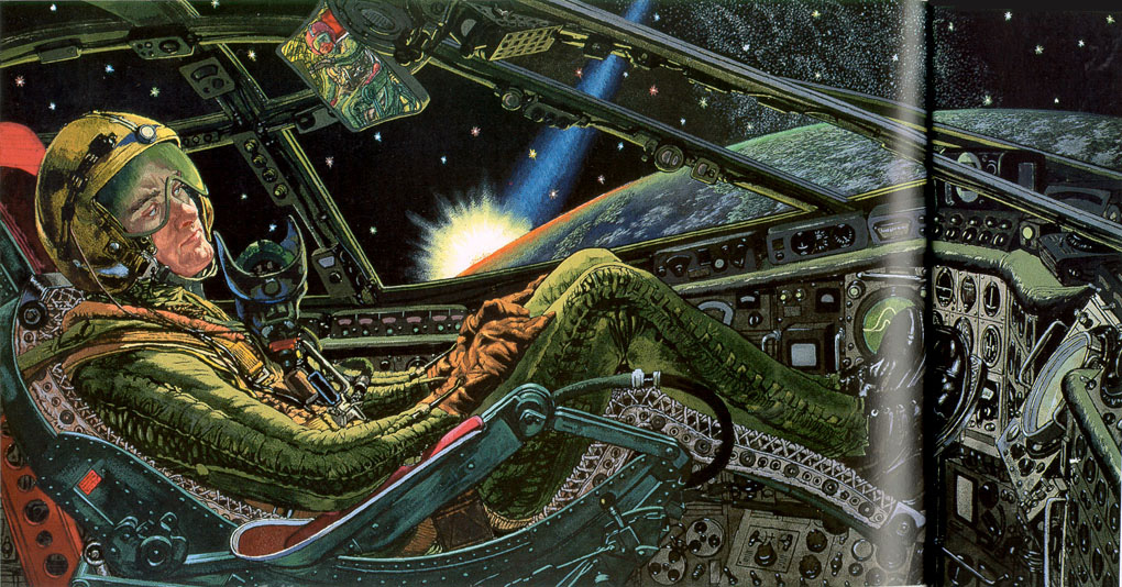
Fascinating. Surely an exceedingly rare work. Unfortunately, no artist’s signature is visible.

Finally, thanks to G's posting of this very image, its associated press slug:

"This is how a General Electric artist envisions the first man in space. The rockets that have propelled him from the earth's surface have fallen away and he is in orbit charting an area never before penetrated by man.

Chicago Daily News,
Chicago 6, Illinois"

The "Chicago" information being exactly what's stamped on the verso of my photograph. Synergy…pretty cool! 😉

a+/fut_v_bw_o_n (Bell Aerosystems Co. photo no. C 26080) by Mike Acs

© Mike Acs, all rights reserved.

a+/fut_v_bw_o_n (Bell Aerosystems Co. photo no. C 26080)

“This artist’s concept depicts one configuration currently being studied by Textron’s Bell Aerosystems Company in conjunction with its one-man Lunar Flying Vehicle preliminary design work for the National Aeronautics and Space Administration’s Manned Spacecraft Center, Houston, Texas. Powered by twin rocket engines, it would be capable of 10-15 mile minimum flight ranges. It also could perform at least 30 sorties and be able to use the residual propellants from the descent stage of the Lunar Module. Mounted to the back of this design is a payload pallet. Motorcycle-like handle grips would be used for thrust and attitude control.”

To my knowledge, the Descent Propulsion System fuel of the Lunar Module was hypergolic. Wouldn’t that’ve been a risky proposition to use?

Note the deployed EASEP/ALSEP components.

Beautiful & iconic (in my world) ca. 1968/69 artwork by Bell Aerosystems’ immensely talented artist, John J. Carr.

See also...always informative & entertaining:

www.aerospaceprojectsreview.com/blog/?s=Bell+Aerosystems&...

Specifically:

www.aerospaceprojectsreview.com/blog/wp-content/uploads/2...
Both above credit: Aerospace Projects Review website/blog

Additional interesting designs:

www.astronautix.com/l/lunarflyers.html
Credit: Astronautix website

fut/lnr_v_bw_o_n (ca. 1958, unnumbered promo photo) by Mike Acs

© Mike Acs, all rights reserved.

fut/lnr_v_bw_o_n (ca. 1958, unnumbered promo photo)

An illustration from Wernher von Braun’s 1958/60 book, “First Men to the Moon”

Too cool. Delightful. Amusing. Entertaining. Intricate. By the hand of the supremely talented Fred Freeman:

www.projectrho.com/public_html/rocket/images/realdesigns/...

With other wonderful images providing context. Make sure to read the associated text & captions of the other images:

www.projectrho.com/public_html/rocket/realdesigns.php
Both above credit: “ATOMIC ROCKETS” website

And, not surprisingly, at John Sisson’s delightful “Dreams of Space” blog:

dreamsofspace.blogspot.com/2013/06/first-men-to-moon-this...

Specifically:

blogger.googleusercontent.com/img/b/R29vZ2xl/AVvXsEhEBTTJ...

5.06” x 9.31”, with a wonderful satin sheen to the image. The photo is dated the same day the serialization of von Braun’s book was published in “This Week Magazine”.

STSprog-fut_v_c_o_AKP (116-KSC-70PC-145) by Mike Acs

© Mike Acs, all rights reserved.

STSprog-fut_v_c_o_AKP (116-KSC-70PC-145)

“Artist Concept - Roll out of space shuttle.
3-23-70”

Best as I can ascertain, with absolutely minimal to go on, this is an early (1969/70) Lockheed Aircraft Company shuttle concept, maybe/maybe not as a part of Phase A. Although I see no windows, based on the time period & complete reusability still being pursued, I assume the flyback booster to be manned.
I believe the open deck barge moored in front of the shuttle is NASA barge “KSC 1”.

And the only reason I have even the above is because of the caption associated with another artist’s concept of the same vehicle. The image & caption are contained within Dennis R. Jenkins’ highly informative book, “Space Shuttle: The History of the National Space Transportation System: The First 100 Missions”. Available at the fantastic Internet Archive website, specifically:

archive.org/details/spaceshuttlehist0000jenk_f6n1/page/90...

If you’ve got a couple of bucks burning a hole in your pocket, send it their way…after of course first donating something/anything toward the welfare of animals.

Mr. Jenkins:

airandspace.si.edu/collection-media/NASM-A20120082000cp01
Credit: NASM website

STSprog-fut_v_c_o_AKP (116-KSC-70PC-145, edited/cropped) by Mike Acs

© Mike Acs, all rights reserved.

STSprog-fut_v_c_o_AKP (116-KSC-70PC-145, edited/cropped)

Just fiddling around with the rudimentary Windows 11 photo editing capability & my equally rudimentary 'skill' using it.

STSprog_v_c_o_AKP (unnumbered ca. 1969-71 NAR photo) by Mike Acs

© Mike Acs, all rights reserved.

STSprog_v_c_o_AKP (unnumbered ca. 1969-71 NAR photo)

A really cool artist's concept of a possible North American Rockwell (NAR) Phase A or B shuttle concept. NAR since the artist is the talented Henry Lozano Jr.
I couldn't find this anywhere, and actually to me, it looks more like a McDonnell design I came across. Nobody seemed to have both fuselage & underbelly mounted air-breathing engines, especially with the underbelly placement being that far forward.
My searching was fruitless despite the aid of this excellent & rather exhaustive document:

archive.org/details/spaceshuttlehist0000jenk_f6n1/page/14...
Credit: Dennis R. Jenkins/Internet Archive website.

I do know it's obviously related to the design of my below linked photo. And I believe it's subsequent to it, only because I read something somewhere stating that the winglets were dropped from consideration. Admittedly, I don't recall if it pertained to NAR.
As I've repeatedly stated, this period of shuttle designs & evolution is confusing to me.