The Flickr Boeingaerospacecompany Image Generatr

About

This page simply reformats the Flickr public Atom feed for purposes of finding inspiration through random exploration. These images are not being copied or stored in any way by this website, nor are any links to them or any metadata about them. All images are © their owners unless otherwise specified.

This site is a busybee project and is supported by the generosity of viewers like you.

fut-spasta_v_c_o_TPMBK (ca. 1981, Boeing Aerospace Co. photo no. B-0866, R-1870, V-2038) by Mike Acs

© Mike Acs, all rights reserved.

fut-spasta_v_c_o_TPMBK (ca. 1981, Boeing Aerospace Co. photo no. B-0866, R-1870, V-2038)

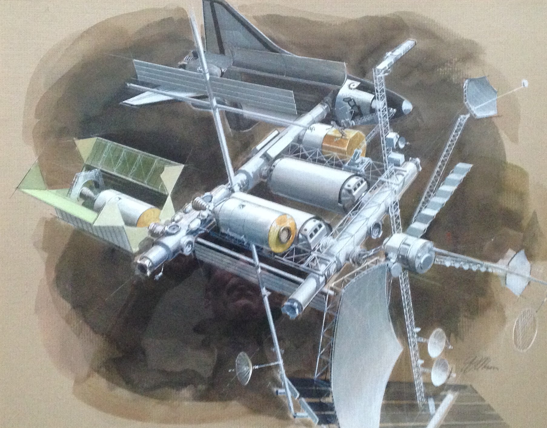
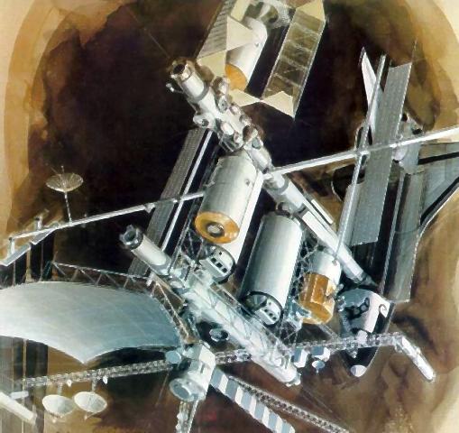
“This designer’s conception shows some of the applications of an advanced Space Operations Center, currently being studied by Boeing Aerospace Company for NASA. This advanced version of the spaceport shows the Space Shuttle unloading some of the modules which would comprise the system. Those modules include living and command control quarters; warehouses for food, water and hydrazine, and service areas containing batteries and other necessary supplies. Other areas of this advanced concept include hangars for spacecraft, solar panels to provide power for the station, and construction equipment to handle large structures. The large structure containing several antenna reflectors is a communications platform which is about to be assembled to an Orbital Transfer Vehicle for a flight to a higher orbit in space.”

Note the interesting truss-work crane/RMS-like device, complete with grappling arms(?), directly "above" the nose of the orbiter. Although the grappling arms, if that’s even what they are, appear to be extending from a secondary, smaller truss-like structure…so I’ve probably misidentified this thing. To complete the descent into this particular hole, the two antennae-looking protrusions, also in the immediate vicinity, look like the work lights associated with Grumman’s Manned Remote Work Station. So, that’s what’s going on here…my final answer. 😉

8.5” x 11”.

Another gorgeous work by Boeing’s John J. Olson. I find the “sketchy/first draft/work-in-progress” appearance to be interesting, this being just one of several like this that I’ve posted.


See also:

spacearchitect.org/portfolio-item/boeing-space-station-de...

Specifically:

spacearchitect.org/wp-content/uploads/2020/04/1-Space-Ope...
Both above credit: SpaceArchitect.org. website

www.astronautix.com/s/spaceoperationscenter.html

Specifically:

www.astronautix.com/graphics/s/soc81nw.jpg
Both above credit: Astronautix website

fut/OTV_v_c_o_TPMBK (1979, Boeing Aerospace Co. photo no. B-0845, SP-51) by Mike Acs

© Mike Acs, all rights reserved.

fut/OTV_v_c_o_TPMBK (1979, Boeing Aerospace Co. photo no. B-0845, SP-51)

“This photo of an Orbital Transfer Vehicle (OTV) shows the upper stage after it has placed a geostationary platform in orbit above the Earth. The totally-reusable liquid-fueled spacecraft is being studied by Boeing Aerospace Company under a contract with NASA’s Marshall Space Flight Center in Huntsville, Alabama. The geostationary platform contains various antenna for communications with Earth. The OTV could place cargo or people into higher orbits in space and be able to return to the Space Shuttle for reuse.”

8.375" x 11.5". Yet another exquisite work by Boeing’s John “Jack” Olson.

Continue to Rest In Peace Brother, and thank you:

www.398th.org/Images/Images_Association/Text/Olson_Cleari...
Credit: 398th Bomb Group Memorial Association website

space.nss.org/national-space-society-governor-jack-olson-...
Credit: NSS website

fut/OTV_v_c_o_TPMBK (1979, Boeing Aerospace Co. photo no. B-0844, SP-50) by Mike Acs

© Mike Acs, all rights reserved.

fut/OTV_v_c_o_TPMBK (1979, Boeing Aerospace Co. photo no. B-0844, SP-50)

“A hypersonic shockwave system envelops an Orbital Transfer Vehicle (OTV) as it grazes the atmosphere on returning to low Earth orbit. The totally-reusable liquid-fueled spacecraft is being studied by Boeing Aerospace Company under a contract with NASA’s Marshall Space Flight Center in Huntsville, Alabama. In this drawing, the vehicle main engine and the ballute, or balloon parachute which encases the OTV, provide protection from the reentry heat and modulate the drag to allow the OTV to enter a lower orbit precisely. After reentering the lower orbit, the ballute would be deflated and the OTV would rendezvous with a Space Shuttle for further assignment.”

The image & further informative reading:

www.secretprojects.co.uk/threads/boeing-otv.4447/

www.secretprojects.co.uk/threads/id-those-aeroassist-vehi...
Both above credit: SECRET PROJECTS FORUM website

books.google.com/books?id=PETCVTz_lwUC&dq=silver+bage...
Credit: Google Books/SECRET PROJECTS FORUM website

Another beautiful work by Boeing’s Jack Olson…who was the Real Deal, in more ways than one:

www.398th.org/Images/Images_Association/Text/Olson_Cleari...
Credit: 398th Bomb Group Memorial Association website

Note that Mr. Olson created the work in October 1979, although it seems to have been ‘popularly’ published/used ca. 1982/83.

All about the ABOTV:

www.researchgate.net/publication/23852064_Aerobraked_orbi...
Credit: ResearchGate website

fut/OTV_v_c_v_TPMBK (1979, Boeing Aerospace Co. photo no. B-0844, SP-50, detached data sheet) by Mike Acs

© Mike Acs, all rights reserved.

fut/OTV_v_c_v_TPMBK (1979, Boeing Aerospace Co. photo no. B-0844, SP-50, detached data sheet)

STSprog/fut_v_bw_v_n (ca. 1970, unnumbered GAC photo) by Mike Acs

© Mike Acs, all rights reserved.

STSprog/fut_v_bw_v_n (ca. 1970, unnumbered GAC photo)

STSprog_v_bw_o_n (ca. 1976-78, Boeing photo poss. no. A-1085 or V-1732) by Mike Acs

© Mike Acs, all rights reserved.

STSprog_v_bw_o_n (ca. 1976-78, Boeing photo poss. no. A-1085 or V-1732)

“INERTIAL UPPER STAGE TO PLACE TRACKING AND DATA RELAY SATELLITES IN ORBIT

Artist’s conception shows two Inertial Upper Stage space tugs each carrying a National Aeronautics and Space Administration Tracking and Data Relay Satellite (TDRS). The Boeing-built IUS has been selected to take four of the six TDRS payloads from the Shuttle’s low Earth orbit to geosynchronous orbit, 22,000 miles above the Earth. The first Space Shuttle/IUS/TDRS launch is scheduled in 1980. The illustration depicts two IUS/TDRS payloads on one Space Shuttle trip, a launch technique that may be used in the future. The illustration shows the method of ejection of the IUS and its payload from the Shuttle bay. The IUS will be mounted on a rotating frame and be ejected by a spring-loaded mechanism. The solid-fueled IUS is being developed by the Boeing Company for both NASA and Department of Defense missions under contract from the U.S. Air Force Space and Missile Systems Organization.”

8.25” x 10.5”. Two of the four sides hand-trimmed.

A beautiful work by veteran Boeing artist Doug Kyes:

sites.google.com/site/kyesillustrator/home
Credit: Doug Kyes/Google

And sadly:

www.rentonwa.gov/news/archived_news/doug_kyes_passes
Credit: City of Renton, WA website

fut/sps_v_bw_o_n (ca. 1977, Boeing Aerospace Co. PR photo) by Mike Acs

© Mike Acs, all rights reserved.

fut/sps_v_bw_o_n (ca. 1977, Boeing Aerospace Co. PR photo)

“FROM FICTION INTO FEASIBLE

The enormous solar power satellite illustrated here could be a first step in the human colonization of space. A Boeing concept shows it as a four-segment array stretching 14.7 miles across space, collecting energy and beaming it back to earth to be transformed into usable electricity. Such concepts may seem like science fiction--but the federal government and large sectors of industry are serious about the ideas and are spending a good deal of time and money to see if they will work.”

Another (better) press release caption:

"This is Boeing's concept of a four-segment solar power satellite stretching 14.7 miles across space. Structures above each solar collection module are panels which radiate unwanted heat from the spherical thermal generators which girdle. The round disks at lower left and upper right are the satellite's transmitters which beam microwaves back to earth where they are transformed into usable electricity."

The official Boeing PR caption:

"Photo shows a Boeing concept of four-segment power power satellite array stretching 14.7 miles (23.7 kilometers) across space. Structures above each solar collection module are panels which radiate unwanted heat from the spherical thermal generators which they girdle. The round disks seen lower left and upper right are the satellite's transmitters which beam microwaves back to Earth where they are transformed into usable electricity."

Based solely on the artist identification of another Boeing SPS concept, possibly by Alden Metcalf.

fut/spasta (OTV)_v_bw_o_TPMBK (ca. 1981/82, Boeing Aerospace Co. photo no. R-1859, V-2034, poss. B-0846) by Mike Acs

© Mike Acs, all rights reserved.

fut/spasta (OTV)_v_bw_o_TPMBK (ca. 1981/82, Boeing Aerospace Co. photo no. R-1859, V-2034, poss. B-0846)

“This artist concept shows an Orbital Transfer Vehicle (OTV) being serviced in the hangar of a Space Station located in low Earth orbit. The hangar serves as a shelter to protect the upper stage spacecraft from space debris and as a maintenance facility between spaceflights. Lighting and easy accessibility are provided for repair and servicing operations. The OTV would be based at the Space Station semi-permanently to allow more flexibility in payload handling and launching. This spacecraft could take up to 10 tons of cargo or people thousands of miles into space and be able to return to its launch orbit for reuse. Boeing Aerospace Company is conducting concept definition studies of the OTV for NASA’s Marshall Space Flight Center in Huntsville, Alabama.”

Looks like the engines of the OTV are going to be changed out. Or, at the very least, the SOC appears to be capable of/equipped to do so.

And/or:

“SOC OTV - 1982
Space Tug / Space Operations Center, 1982. NASA/Johnson also regarded the space tug as an integral component of its Space Operations Center plan. This Boeing illustration from 1982 depicts a space tug being serviced inside its hangar onboard SOC.

Credit: NASA via Marcus Lindroos”

The above & image (in color) at/from:

www.astronautix.com/o/otv.html

Specifically:

www.astronautix.com/graphics/s/soc82otv.jpg

And:

www.pmview.com/spaceodysseytwo/station/sld006.htm
Credit: PMView Pro website

Yet another testament to John J. Olson’s talent…the attention to detail, shading, perspective, etc., etc.

8.375” x 11”.

fut/sps_v_bw_o_n (1977, Boeing Aerospace Co. PR photo no. V 1644) by Mike Acs

© Mike Acs, all rights reserved.

fut/sps_v_bw_o_n (1977, Boeing Aerospace Co. PR photo no. V 1644)

“Photo shows Boeing conception of a photovoltaic (solar cell) power satellite being constructed in low Earth orbit. A Space Shuttle Orbiter (upper right) docks at the facility’s assembly bay. To the left, an upper stage of a heavy lift launch vehicle approaches the facility to discharge its cargo of construction material. The weightlessness of space allows the use of weblike structures of a sort which would be crushed if used on Earth. The satellite would be deployed in geosynchronous orbit after completion.”

Above per the affixed official Boeing caption, below from the affixed associated newspaper clipping:

“Boeing Spaces Out on a Sunny Idea

A mammoth solar energy satellite dwarfs a space shuttle orbiter (arrow, upper right) docking at the facility’s assembly bay in this sketch from the Boeing Co. To the left, an upper stage of a heavy launch vehicle approaches the facility to discharge its cargo of construction material. The weightlessness of space allows the use of weblike structures of a sort which would be crushed on earth. The satellite could be erected 22,000 miles above earth, in a fixed orbit, and transmit power to a receiving system on the ground. It would cover 50 square miles, equivalent to the area of a small city and would supply enough electricity for a million homes. The sun’s power collected by the satellite would be beamed to earth in the form of microwaves, which in turn would be converted to usable electricity. Boeing’s Ralph Nansen, manager of space-based solar power systems, says it’s an idea whose time has come.”

8.5” x 11”. The markings along/within the white border clearly identify this as having been used as the source for press reproduction. Interestingly, a previous ‘owner’ had already attempted to remove the markings, which were in pencil fortunately. The slightly faded area to the immediate upper right of the orbiter is where the referenced (and at some point, affixed) arrow had been removed.
Gorgeous work by John J. Olson, and pretty much iconic (in my world), when it comes to Solar Power Satellites. Despite that, there doesn’t seem to be a high-resolution version of it anywhere, not even at the arrogant “Boeing Secure Image” website.
Finally, for purists…or probably just purist, WITH the official Boeing photo number AND caption. BFD
though I suppose. If nothing else, at least now there’s a high-res black & white version online. Yay.

The second image at the following link, and diagram below it, looks to be the referenced Heavy Lift Launch Vehicle (HLLV):

www.pmview.com/spaceodysseytwo/spacelvs/sld044.htm
Credit: PMView Pro website

If so, which I never really paid attention to before, the eight engines visible on the HLLV were to each have been a Space Shuttle Main Engine (SSME). Damn, who knew? Did you??? I didn’t!!!

And finally, trivial & obscure, which I’m all about, note the apparent “SSI” logo…I think. I’ve passingly noted it before, without giving it really any consideration. However, now, FINALLY, due to the high resolution, after 44+ years, which I didn’t even know was there, printed beneath the SSI lettering is…”SUNSAT SPACEWAYS”…maybe followed by “INC”, it’s kind of blurred. Tah Dah! Yet another one-off WIN. Yay II.
In all seriousness, yet another gorgeous & detailed work by Jack Olson.

Jack Olson, continue to Rest In Peace Brother. Thank You:

www.398th.org/Images/Images_Association/Text/Olson_Cleari...
Credit: ‘398th Bomb Group Memorial Association’ website

space.nss.org/national-space-society-governor-jack-olson-...
Credit: National Space Society (NSS) website

fut-spasta_v_bw_o_TPMBK (ca. 1980, unnumbered Boeing Aerospace Co. promo photo) by Mike Acs

© Mike Acs, all rights reserved.

fut-spasta_v_bw_o_TPMBK (ca. 1980, unnumbered Boeing Aerospace Co. promo photo)

“NO, THIS NOT a scene from the movie 2001, but an artist’s conception of what a Boeing - built spaceport might look like, when and if such a structure becomes a reality. Boeing Aerospace Co. is studying this “versatile operations base in space” under terms of a $400,000, year-long contract with NASA. Geared to the flights of the space shuttle (shown upper left), the space station would orbit about 250 miles above the Earth. It would have mainly operational, rather than scientific, functions. A crew of four could man the spaceport by the late 1980s, officials said. – Drawing by John J. Olson.”

Due to its larger size (8.625" x 11"), along with being on Kodak paper, I'm pretty sure this was part of some polished, professional Boeing presentation portfolio/packet.

Exquisite detail and a masterful depiction of multiple geometric perspectives, shadows/shading…you name it…a walk-in-the-park for John J. Olson. Gratifying to see him called out in the description/caption. The man – not just the artist – was most deserving of it:

www.398th.org/Images/Images_Association/Text/Olson_Cleari...
Credit: 398th Bomb Group Memorial Association website

fut/spasta_v_c_o_TPMBK (ca. 1985, Boeing photo, verso hand-annotated R-2126) by Mike Acs

© Mike Acs, all rights reserved.

fut/spasta_v_c_o_TPMBK (ca. 1985, Boeing photo, verso hand-annotated R-2126)

“The NASA Space Shuttle unloading some cargo which will comprise the Space Station system, in a design by the Boeing Aerospace Company for NASA.”

8.375” x 11”. Dramatic depiction by the man, John J. Olson. I like his ghost-like allusion to future expansion. Note also what looks like a Boeing-version/design? of a space tug, in front of the shuttle, possibly berthed to the space station. Also, slightly below & to the left of it, the enclosed servicing bay.
I don't have it in me to try to identify which design, phase, iteration, etc., this is. Space Operations Center (SOC) maybe? Planar? If indeed 1985 or subsequent, maybe the core elements of a dual-keel configuration? Ugh.

Above, along with the image, at:

www.granger.com/results.asp?inline=true&image=0185268...
Credit: Granger Historical Picture Archive

Pay-to-play, but at least they put it out there, and ‘oh well’.

Last, but NOT least. Jack Olson:

www.398th.org/Images/Images_Association/Text/Olson_Cleari...
Credit: 398th Bomb Group Memorial Association website

space.nss.org/national-space-society-governor-jack-olson-...
Credit: NSS website

STS+fut_v_c_o_TPMBK (B-0871, R-1904, V-2082, ca. 1982 Boeing PR photo) by Mike Acs

© Mike Acs, all rights reserved.

STS+fut_v_c_o_TPMBK (B-0871, R-1904, V-2082, ca. 1982 Boeing PR photo)

“This artist’s drawing shows a basic design concept for the proposed Shuttle Derived Cargo Launch Vehicle. The vehicle consists of a shortened Space Shuttle external tank in the center of the artwork. A single Space Shuttle main engine is mounted below the tank and two shortened Space Shuttle solid rocket boosters are mounted on each side. A large cannister shroud containing the upper stage and payload sits above the launch vehicle. The vehicle concept is being studied by Boeing Aerospace Company under contract to NASA Marshall Space Flight Center, Huntsville. Alabama.”

8.375" x 11".

As always, interesting reading & good info. See specifically the April 30, 2008 post by user “starviking”:

www.secretprojects.co.uk/threads/the-jarvis-launcher.4307/
Credit: SECRET PROJECTS website

Also…again, always excellent information:

www.spacelaunchreport.com/sdv.html

Specifically, at the far left:

www.spacelaunchreport.com/sdv1.jpg
Both above credit: Space Launch Report website

While the above is all fine & dandy, nostalgic (which I’m normally all about) & possibly bittersweet, especially since it never happened – along with SO MANY other visionary & creative ideas – what really matters here is that the artwork is by none other than John J. Olson, “the MAN”.

Proof of the last statement:

www.398th.org/Images/Images_Association/Text/Olson_Cleari...

www.398th.org/PDF/Images_Association/Olson_ClearingandCol...

space.nss.org/national-space-society-governor-jack-olson-...

To me, it looks to be a work in progress…apparently from December 1980. The crane, multiple lines that I think otherwise would’ve been erased/painted over, the muted/preliminary(?) coloring. And most obvious I believe, the transparent appearance of the foreground tail service mast and other GSE…you can see what appears to be the curve of the flame deflector “through” it, along with the outline of the left SRB through whatever the other structure is.
All of the above are very “un-Olson-like”. Throughout his career, his striking works look complete,. They’re crisp, bold & definitive.

fut_v_bw_o_n (B-0511, R-0879, V-1192, ca. 1979 (& 1992) Boeing PR photo) by Mike Acs

© Mike Acs, all rights reserved.

fut_v_bw_o_n (B-0511, R-0879, V-1192, ca. 1979 (& 1992) Boeing PR photo)

“Photo shows engineers’ concept of a four-segment power satellite array stretching 9.4 miles (15 km) across space. Craft lower right is one of the solar electric propulsion stages which help carry the four modules individually from low Earth orbit to geosynchronous orbit. Another barely can be seen attached to the right corner of the first module of the array. The two wing-like structures above each solar collection module are panels which radiate unwanted heat from the thermal generators located at the apex of the segment’s structure. The round disk seen lower left is the satellite’s transmitter which beams microwaves to Earth where they are transformed into usable electricity.”

Interesting observation/commentary by the proprietor of “The Unwanted Blog” blog, with additional observations/commentary by followers, I think of this very photo:

“...depicting a Boeing concept for a solar power satellite from the 1970’s. Most SPS concepts were for Manhattan-sized slabs of aluminum trusswork, holding vast fields of photovoltaic cells. This design, though, was different in that it was a Manhattan-sized collection of vast reflectors concentrating sunlight onto relatively small targets. There a working fluid would be super-heated and the resulting high-pressure gas blown through turbo-generators. The gas would be cooled and condensed in the radiators. Note that the artist took some liberties with the orientation: a setup like this would only work if the reflectors were reasonably precisely aligned with the sun. That would only occur when the shadow of the solar collector at the focal point fell onto the center of the concentrating mirror assembly; the radiators would cast almost no shadow, just a razor-thin line bisecting the mirrors.”

At:

up-ship.com/blog/?p=38483

And (with other wonderful images):

www.aerospaceprojectsreview.com/blog/?m=201808

Finally, with additional commentary/observations:

beastrabban.wordpress.com/2015/12/18/forget-fracking-spac...

AGM-86A Cruise Missile, U. S. Air Force, National Air and Space Museum's Steven F. Udvar-Hazy Center, Virginia, Chantilly by EC Leatherberry

© EC Leatherberry, all rights reserved.

AGM-86A Cruise Missile, U. S. Air Force, National Air and Space Museum's Steven F. Udvar-Hazy Center, Virginia, Chantilly

The AGM-86A was the first version of the U/ S. Air Force's air-launched cruise missile (ALCM). Designed to carry either a conventional or nuclear warhead, it had a turbofan jet engine, flew at subsonic speeds, and used an inertial navigation system with terrain contour- matching radar. Because the missile flew close to the ground it was difficult for enemy radars to detect.

Most AGM-86As were used in flight test in 1976. The missile never became operational. Subsequent versions of the ALCM with conventional or nuclear warheads and longer range have been produced and deployed on B-1 and B-52 bombers. (Source: National Air and Space Museum's Steven F. Udvar-Hazy Center)