The Flickr Satellitedeployment Image Generatr

About

This page simply reformats the Flickr public Atom feed for purposes of finding inspiration through random exploration. These images are not being copied or stored in any way by this website, nor are any links to them or any metadata about them. All images are © their owners unless otherwise specified.

This site is a busybee project and is supported by the generosity of viewers like you.

STSprog/fut_v_c_o_AKP (ca. 1970/71, MDAC photo no. POGP 316-870) by Mike Acs

© Mike Acs, all rights reserved.

STSprog/fut_v_c_o_AKP (ca. 1970/71, MDAC photo no. POGP 316-870)

Very nice ca. 1970/71 overhead view of a Phase-B McDonnell Douglas Astronautics Company (MDAC) shuttle in orbit.

Damned if I could find any matches for this design. No central vertical stabilizer, instead with “them” at the wingtips. Are they still referred to as vertical stabilizers out there? Are they instead winglets? Or are they too big to be referred to as winglets? And because of this appearance, it has a “baseline” NASA-designed orbiter look to it, from ca. 1969…I think. Being a MDAC 'consortium' entry, it also looks like a Spacemaster derivative/evolution. Further confusion (for me) was what appears to be a single main engine, which was never the case for any orbiter design, ever…to my knowledge. Despite the perspective, the second one should’ve still been at least marginally visible/depicted IMHO.

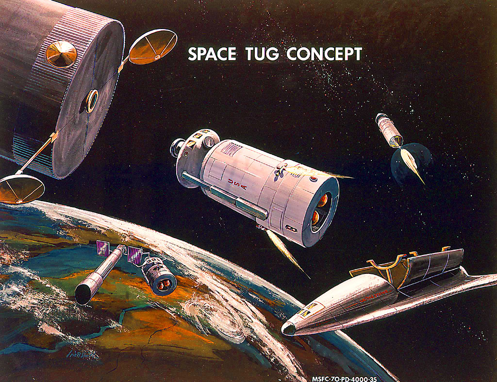
Finally, note the dual/double-decker/two-for-one communications(?) satellite deployment configuration, them being attached to a…what…space tug/Orbital Transfer Vehicle? If so, it should be reusable, right. Is it? And look how wide it is, with the way the propellant(?) tanks are mounted to the “bus”. Does this sort of confirm this hangs out in orbit, waiting to be employed, as is apparently the case here. Can the tanks be jettisoned, in order to be positioned/stowed in the payload bay, say for repairs or refurbishment. I doubt it would be secured transversely, with all tanks still attached.
And then there’s the payload still in the payload bay, with what appear to be the same type/size of tanks, but, mounted to the end of its bus, instead of ringing it, as in the deployed stack.
Further fuel for the murky, amorphous, dynamic, and confusing (to me) Phase-A —> Phase-B shuttle thing.

Oh yeah, one more…check out the 1950’s ray-gun looking gizmo deployed at the back corner of the payload bay. Rendezvous radar? Communications antenna?

A similar double satellite deployment scenario is linked to below.

STS46_v_c_o_TPMBK (STS046-73-067) by Mike Acs

© Mike Acs, all rights reserved.

STS46_v_c_o_TPMBK (STS046-73-067)

“The STS-46 crewmembers used a 70mm handheld camera to capture this image of the Tethered Satellite System (TSS) as it shared the scene with a half-moon. Five NASA astronauts were joined by two Europeans for eight days aboard the Atlantis in Earth orbit.”

Based on the digital(?) camera date/data “stamp” of the following linked image, and what I assume to be its correct/natural/original orientation, I’ve commensurately oriented my photo:

garystockbridge617.getarchive.net/amp/media/s46-73-067-st...
Credit: picryl website

Good reading:

www.americaspace.com/2022/07/31/weird-science-remembering...
Credit: AmericaSpace website

Shitty & cursory reading:

www.nasa.gov/mission/sts-46/

Excruciatingly, but interestingly (to me) detailed reading:

ntrs.nasa.gov/api/citations/19930016042/downloads/1993001...

STSprog_v_bw_o_TPMBK (unnumbered, verso hand-annotated SPL78, S81-36161 eq) by Mike Acs

© Mike Acs, all rights reserved.

STSprog_v_bw_o_TPMBK (unnumbered, verso hand-annotated SPL78, S81-36161 eq)

“Rockwell art concept view of Shuttle in orbit with open cargo bay showing the Global Positioning System sortie pallet.”

What’s a GPS “sortie” pallet??? All I know is that it was a term used earlier during the consideration/development of shuttle payloads.

www.dvidshub.net/image/701710/rockwell-art-concept-view-s...
Credit: DVIDS website

This is an absolutely exquisite piece of shuttle-related artwork…seriously. And the photo surface has a super-fine satin sheen to it, which really accentuates the aesthetic appeal.
But, by whom? Henry Lozano maybe? Manuel Alvarez? Somebody else? It almost looks like the interesting cloud formations may contain cleverly jumbled letters. ¯\_(ツ)_/¯

STSprog/fut_v_c_o_AKP (ca. 1970/71, unnumbered NAR/NASA photo) by Mike Acs

© Mike Acs, all rights reserved.

STSprog/fut_v_c_o_AKP (ca. 1970/71, unnumbered NAR/NASA photo)

Absolutely striking artwork depicting what I believe to be a North American Rockwell, Phase-B shuttle concept, specifically, the “161 C Configuration”, based on user flateric’s 4 June 2007 posting, at the following link:

www.secretprojects.co.uk/threads/various-us-reusable-laun...
Credit: SECRET PROJECTS FORUM website

See also:

nss.org/the-space-shuttle-decision-chapter-8/
Credit: NSS website

And:

www.astronautix.com/s/shuttler134c.html
Credit: Astronautix website

I have no idea what it’s deploying, retrieving, or servicing…whether it’s a satellite, space station component…or some sort of space tug. Actually, who cares.
And check out the cool domed cupola sort of thing just forward of the payload bay doors. Possibly where the RMS (although I don't see such) operator sits? You can even see the outlines of the doors to the stowed air-breathing engines, to include being able to surmise that each pair are opposingly hinged. This is a masterpiece...both artwork & orbiter.

No signature, drat it. NAR…1970/71…hmm:
Henry Lozano Jr.?
Manuel E. Alvarez?
Bert Winthrop?
¯\_(ツ)_/¯

fut/OTV_v_c_o_TPMBK (1979, Boeing Aerospace Co. photo no. B-0845, SP-51) by Mike Acs

© Mike Acs, all rights reserved.

fut/OTV_v_c_o_TPMBK (1979, Boeing Aerospace Co. photo no. B-0845, SP-51)

“This photo of an Orbital Transfer Vehicle (OTV) shows the upper stage after it has placed a geostationary platform in orbit above the Earth. The totally-reusable liquid-fueled spacecraft is being studied by Boeing Aerospace Company under a contract with NASA’s Marshall Space Flight Center in Huntsville, Alabama. The geostationary platform contains various antenna for communications with Earth. The OTV could place cargo or people into higher orbits in space and be able to return to the Space Shuttle for reuse.”

8.375" x 11.5". Yet another exquisite work by Boeing’s John “Jack” Olson.

Continue to Rest In Peace Brother, and thank you:

www.398th.org/Images/Images_Association/Text/Olson_Cleari...
Credit: 398th Bomb Group Memorial Association website

space.nss.org/national-space-society-governor-jack-olson-...
Credit: NSS website

fut (MSFC-70-PD-4000-35, 'Atomic Rockets' website download) by Mike Acs

© Mike Acs, all rights reserved.

fut (MSFC-70-PD-4000-35, 'Atomic Rockets' website download)

“SPACE TUG CONCEPT”

“Space Tug: Boeing

The Boeing Space Tug is a modular design. This concept was later developed into the NASA Space Tug. One way to tell the difference is that the Boeing tug's crew and cargo modules were spherical, while the NASA tug's modules were cylindrical.”

The above & image at/from

www.projectrho.com/public_html/rocket/spacetug.php#spacetug

Specifically:

www.projectrho.com/public_html/rocket/images/realdesigns/...
Credit both above: ATOMIC ROCKETS website

The signature looks to be that of Lois A. Smith, hence my posting, and therefore, a WIN.

HST_v_c_o_TPMBK (1985, unnumbered Lockheed/NASA photo) by Mike Acs

© Mike Acs, all rights reserved.

HST_v_c_o_TPMBK (1985, unnumbered Lockheed/NASA photo)

Lockheed artist Gordon Raney’s 1985 depiction of the Hubble Space Telescope (HST), berthed to the Flight Support System (FSS) within the orbiter vehicle’s payload bay, during a ‘maintenance & refurbishment’ mission.

My original thought regarding what's transpiring here was 'artistic license'; however, vague recollection & additional research reveals that HST was reboosted during servicing missions 1, 2 & 3B...which would then also explain the undeployed configuration of the solar arrays. Additionally, I suppose the angled positioning of HST would also reduce the torque/stress on its structure during the reboost.

esahubble.org/about/history/sm3b_a_little_boost/#:~:text=....
Credit: ESA/Hubble website

And since one or two of you were (or eventually will be) thinking “I wonder how’d that whole HST/orbiter berthing thing/system work?” Although some of it’s Servicing Mission 4 (SM-4) specific, it’s still applicable to any/all of the servicing missions:

“Flight Support System

The FSS is a maintenance platform used to berth the HST in the payload bay after the Atlantis crew has rendezvoused with and captured the telescope (see Fig. 2-4). The platform was adapted from the FSS first used during the Solar Maximum repair mission and was converted to use with HST. It has a U-shaped cradle that spans the rear of the bay. A circular berthing ring with three latches secures the telescope to the cradle. The berthing ring can rotate Hubble almost 360 degrees (176 degrees clockwise or counterclockwise from its null position) to give EVA astronauts access to every side of the telescope.

The FSS also has the capability to pivot the telescope, if required for servicing or reboosting. The FSS’s umbilical cable provides power from Atlantis to maintain thermal control of the telescope during the servicing mission.

On SM4 the FSS also carries a Soft Capture Mechanism (SCM) on its berthing and positioning system platform. When attached to the HST aft bulkhead, the SCM will enable and assist in the safe de-orbit of the telescope at the end of its useful life by providing a docking interface that is intended to be compatible with future launch vehicles.”

At/from:

www.nasa.gov/pdf/327688main_09_SM4_Media_Guide_rev1.pdf

Unfortunately, nothing on Mr. Raney.

STS31_v_c_o_TPMBK (STS-31-04-27, neg. no. 9013404) by Mike Acs

© Mike Acs, all rights reserved.

STS31_v_c_o_TPMBK (STS-31-04-27, neg. no. 9013404)

“STS-31 onboard photo – HST deployed”

A rarely seen image of the initial deployment of the Hubble Space Telescope (HST). Taken from one of the aft-facing flight deck windows, the close proximity & dramatic perspective indicates it to have been taken early in the deployment process.
Note the prominent dish of one of the two still retracted high-gain antennas, along with the still retracted & rolled up solar arrays along either side.
Finally, note also the abundance of handrails on HST, to facilitate the unprecedented human maintenance of the engineering marvel.

I hope so, very much:

www.nasa.gov/feature/goddard/2022/nasa-spacex-to-study-hu...

fut_v_c_o_AKP (NASA S-69-4053) by Mike Acs

© Mike Acs, all rights reserved.

fut_v_c_o_AKP (NASA S-69-4053)

"Proposed space transportation system is a multi-mission oriented concept. Space shuttle, at upper left, releases an unmanned observatory. The space station in modularized form is at right. The precursor Saturn 5 workshop is at lower left.”

The above caption is associated with the same exact image, posted Sep. 19, 2018, by user "hesham" at the SECRET PROJECTS FORUM website. Although not specified, the image & caption are possibly from an unidentified issue of AW&ST magazine:

At:

www.secretprojects.co.uk/threads/us-space-shuttle-project...

Another identical image, other than the “unmanned observatory” deployment, and linked to below, bears the following description on the verso:

“SPACE STATION---Artist concept of an Earth-orbiting space station as planned by National Aeronautics and Space Administration engineers. A station similar to this will provide broad support for such Earth resource activities as oceanography, meteorology and geophysics. It is capable of supporting biomedical laboratories, physical science laboratories, and solar and stellar observatories. Free-flying modules containing special scientific equipment might orbit near the station. Scientists will travel to the science module in miniature taxis or tugs. The modular concept shown here will have both zero and artificial gravity. It will be able to accommodate between 12 and 50 scientific and technical personnel and it will orbit the Earth at approximately [225?] nautical miles altitude. By adding more modules, the station can become a base from which planetary missions can depart. A station similar to this might also be placed in lunar orbit to support future exploration of the Moon. It will have a Ward Room for crew off-duty activities, food preparation and dining. There will be individual Crew Quarters, Docking and Cargo-Handling [unreadable, if even present]. The crew will probably be rotated at three to six-month intervals. They will be ferried to the station in a shuttle vehicle which will have the capability of landing at airports as do the present-day passenger aircraft. Electric power will come from solar panels or small nuclear [reactors/generators?]. [Launch?] of the initial module could come as early as [1985/86?]. Because of its size, the station will be visible to the naked eye. It [will be visible?] as far north as Ketchikan, Alaska, [and as far south as?] [unreadable] in South America."

Yet another near identical image, sans the “unmanned observatory” deployment, is also linked to below. It may be an earlier version, with different markings visible on the shuttle vehicles.

Finally, as with my previous posting, the ‘framing’ of the image reveals the artist. That being NASA’s Jerry L. Elmore, who, in my world, is most recognized for his memorable renderings of the Apollo 15, 16 & 17 landing sites. Those made ‘famous’ by being featured in the Tang fold-out posters. Another WIN.

And…neither here nor there, but the small land masses are the islands of the Bahamas.

STSprog-fut_v_c_o_AKP (ca. 1970, prob GAC photo, verso hand-annotated 701361) by Mike Acs

© Mike Acs, all rights reserved.

STSprog-fut_v_c_o_AKP (ca. 1970, prob GAC photo, verso hand-annotated 701361)

Striking ca. 1970 Grumman Aerospace Corporation (GAC) artist’s concept depicting a tailless, possible Phase-B space shuttle proposal either servicing, retrieving or deploying an unidentified satellite. I’ve been unable to find anything substantive regarding this tailless design, only passing references to the probable instability of such. Other than that, its appearance is that of the GAC “Design 518 (primarily)/Design 523” proposal:
ntrs.nasa.gov/api/citations/20160012503/downloads/2016001...
…so I assume it to be a briefly considered precursor to those.

A low-resolution black & white version of the image was posted to the SECRET PROJECTS Forum website by user “hesham” on March 20, 2020, taken from a French publication/document, referred to as “Aviation magazine 1969 & 1970”. A loose translation of its accompanying description is “A second Grumman project has a ‘lifting body’ design”.

Last but not least; since all previous versions I’ve seen of this have been of low resolution, I never thought to take a closer look at the two astronauts conducting the EVA. Are those flashlights in their hands? And there appear to be appendages sticking out from their PLSS’s. If so, possibly as part of their AMU/MMU?

Possibly/probably the beautiful work of Craig Kavafes?

STSprog/HST_v_c_o_TPMBK (S86-30462) by Mike Acs

© Mike Acs, all rights reserved.

STSprog/HST_v_c_o_TPMBK (S86-30462)

A gorgeous, even if somewhat over-the-top depiction of, what to me looks a lot like a Hubble servicing mission. Note the non-tethered MMU-wearing Astronauts, representing the heady & all too cavalier vision of what future EVAs would look like. Note also that the orbiter is without the Remote Manipulator System arm…hmm.
Disappointingly/per SOP, the NASA photo whoevers botched the layout of the image; to include the ‘landscape’ orientation and the excessive cropping, lopping off half of the shuttle & half of HST’s aperture door and, in the process, the artists’ signatures.

The complete image was featured on the cover of the 2015 Winter Issue of “Pulsar”, the bi-annual newsletter of the International Association of Astronomical Artists (IAAA), at:

iaaa.org/CygnusX1/wp-content/uploads/2021/01/Pulsar-2015-...
Credit: IAAA website

Within the newsletter, per the artist responsible, Rick Sternbach:

“Science Digest, Astronomy, and Sky & Telescope all featured this painting of the HST done as a collaboration between myself and Don Dixon. Extensive use of airbrush and acrylics, a similar rendering style, and detailed CAD drawings from Lockheed Sunnyvale allowed us to produce this orbital view a few years before Hubble was launched.”

With a flipped "order of billing", reference to it being Perkin-Elmer copyrighted & dated 1984. ¯\_(ツ)_/¯:

www.cosmographica.com/spaceart/Technology/index.html#img=...
Credit: Cosmographica website

Regardless, as a card-carrying member of IAAA’s peanut gallery - if you have even the slightest interest in this type of artwork - I highly recommend taking a look at the following gallery. I can attest that IAAA members are conscientious & consummate professionals constantly striving to create meaningful works:

iaaa.org/artworks_and_news/

STSprog/fut_v_bw_o_n (ca. 1970/71, unnumbered GAC photo) by Mike Acs

© Mike Acs, all rights reserved.

STSprog/fut_v_bw_o_n (ca. 1970/71, unnumbered GAC photo)

“SPACE SHUTTLE ORBITER CONCEPT

Artist’s concept showing orbiter stage of the shuttle system delivering a proposed future optical space telescope into earth orbit. The orbiter is equipped with a remotely controlled telescoping manipulator arm stowed in the cargo compartment, which aids in retrieval and deployment of such payloads. Grumman has recently completed and submitted to NASA a study for the cost saving which would be realized if the shuttle was used to launch and resupply an optical space telescope. The manipulator arm could also be used for the assembly of modularized type space stations. Grumman Aerospace Corporation and the Boeing Company are now conducting a concept comparison and program definition study of a space shuttle system for the National Aeronautics and Space Administration.”

Based on the year, I’m assuming it’s a Phase-B concept; however, I’ll be damned if I can find anything anywhere else that resembles it, especially with that wing/tail combination. Safe to assume the “optical space telescope” is what was to become the Hubble Space Telescope?

Nice to finally see this at this resolution. By Craig Kavafes…outstanding.

STSprog_v_bw_o_n (NASA HQ MH72-5018, 72-H-186) by Mike Acs

© Mike Acs, all rights reserved.

STSprog_v_bw_o_n (NASA HQ MH72-5018, 72-H-186)

“SPACE SHUTTLE---will be a manned reusable space vehicle which will carry out various space missions in Earth orbit. It will consist of two stages. The first stage booster will be an unmanned liquid- or solid-fueled rocket. The second stage orbiter will look like a delta-winged airplane and will be piloted by two men who will fly it back to Earth for an airplane-like landing. On the launch pad the orbiter will be mounted to the booster, which will launch the orbiter to an altitude of about 55 to 65 kilometers (approximately 35 to 40 miles). The orbiter with its payload and crew will detach and continue into Earth orbit for missions lasting about seven days, or possibly as long as 30 days. The man-operated space shuttle orbiter will deploy in Earth orbit all types of scientific and applications satellites weighing up to 29,500 kilograms (65,000 pounds) and thereby replace most of the expendable launch vehicles currently used.”

Note the generic ‘Space Transportation System’ logo in the upper left-hand corner. Possibly an earlier Phase B configuration/design? Or maybe, they just grabbed whoever was nearest the water cooler, gave him a crayon & told him to "draw an airplane". Whatever it is, it doesn’t represent what’s depicted in the image. And God only knows what landmass & lakes possibly...are depicted on the earth? below.

Very nice unidentified artwork. Possibly by Manuel E. Alvarez? Although the depiction of the earth’s limb doesn’t, the clouds suggest such...I think. ¯\_(ツ)_/¯

STS46_v_c_o_TPMBK (STS046-073-052) by Mike Acs

© Mike Acs, all rights reserved.

STS46_v_c_o_TPMBK (STS046-073-052)

“A 70mm handheld camera was used by the STS-46 crewmembers to capture closeup view of early operations with the Tethered Satellite System (TSS). The sphere can be seen moving away from the ring structure on the boom device in Atlantis’ cargo bay.”

From the STS-46 press kit:

“An exciting new capability for probing the space environment and conducting experiments will be demonstrated for the first time when the NASA/Italian Space Agency Tethered Satellite System (TSS-1) is deployed during the STS-46 Space Shuttle flight. The reusable Tethered Satellite System is made up of a
satellite attached to the Shuttle orbiter by a super strong cord which will be reeled into space from the Shuttle's cargo bay. When the satellite on its cord, or tether, is deployed to about 12 miles above the orbiter, TSS-1 will be the longest structure ever flown in space.

Operating the tethered system is a bit like trolling for fish in a lake or the ocean. But the potential "catch" is valuable data that may yield scientific insights from the vast sea of space. For the TSS-1 mission, the tether -- which looks like a 12-mile-long white bootlace -- will have electrically-conducting metal strands in its core. The conducting tether will generate electrical currents at a high voltage by the same basic principle as a standard electrical generator -- by converting mechanical energy (the Shuttle's more than 17,000-mile-an hour orbital motion) into electrical energy by passing a conductor through a magnetic field (the Earth's magnetic field lines).

TSS-1 scientific instruments, mounted in the Shuttle cargo bay, the middeck and on the satellite, will allow scientists to examine the electrodynamics of the conducting tether system, as well as clarify their understanding of physical processes in the ionized plasma of the near-Earth space environment.

Once the investigations are concluded, it is planned to reel the satellite back into the cargo bay and stow it until after the Shuttle lands.

The TSS-1 mission will be the first step toward several potential future uses for tethers in space now being evaluated by scientists and engineers. One possible application is using long conducting tethers to generate electrical power for Space Station Freedom or other orbiting bodies. Conversely, by expending electrical power to reverse the current flow into a tether, the system can be placed in an "electric motor" mode to generate thrust for orbit maintenance. Tethers also may be used to raise or lower spacecraft orbits. This could be achieved by releasing a tethered body from a primary spacecraft, thereby transferring momentum (and imparting motion) to the spacecraft. Another potential application is the creation of artificial gravity by rotating two or more masses on a tether, much like a set of bolas.

Downward deployment (toward Earth) could place a satellite in regions of the atmosphere that have been difficult to study because they lie above the range of high-altitude balloons and below the minimum altitude of free-flying satellites. Deploying a tethered satellite downward from the Shuttle also could make possible aerodynamic and wind tunnel type testing in the region 50 to 75 nautical miles above the Earth.”

At:

spacepresskit.files.wordpress.com/2012/08/sts-46.pdf
Credit: spacepresskit/wordpress website

Reality:

“TSS deployment was also delayed one day because of EURECA. During TSS deployment, the satellite reached a maximum distance of only 840 feet (256 meters) from orbiter instead of planned 12.5 miles (20 kilometers) because of a jammed tether line. After numerous attempts over several days to free the tether, TSS operations were curtailed and satellite was stowed for return to Earth.”

Above from/at:

www.nasa.gov/mission_pages/shuttle/shuttlemissions/archiv...

STSprog-fut_v_c_o_AKP (ca. 1971, unnumbered poss. NAR photo2) by Mike Acs

© Mike Acs, all rights reserved.

STSprog-fut_v_c_o_AKP (ca. 1971, unnumbered poss. NAR photo2)

Circa 1971 montage of (I think) a North American Rockwell artist’s concept depicting a typical mission profile of a fully reusable Phase-B Space Shuttle.

Based primarily on the appearance of the flyback booster, specifically its extended & exposed main engine components, the color palette used, and to a lesser extent, the appearance of the orbiter, to include its protruding main engines (vice the flush appearance of other versions/designs), possibly the work of Bert Winthrop.
Other works supporting my guess are linked to below.
I’ve never seen any of these vignettes as stand-alone works, let alone all together. And this is the first time I’ve ever seen the orbital maneuvering system engines of this particular orbiter design depicted in use…along with both the orbiter & flyback booster under one roof between flights. The flyback booster is even smiling.
I like the textured background, especially visible along the right-hand edge.

STSprog-fut_v_c_o_AKP (ca. 1971, unnumbered poss. NAR photo) by Mike Acs

© Mike Acs, all rights reserved.

STSprog-fut_v_c_o_AKP (ca. 1971, unnumbered poss. NAR photo)

Circa 1971 montage of North American Rockwell artist’s concepts depicting primarily satellite/spacecraft retrieval/deployment & servicing by the future Space Shuttle.

Tantalizingly, the center vignette appears to have an artist’s signature in the lower right. No idea. Although, the image below it has a Gjertson look to. Is it/Would it have been reasonable to expect the vignettes of this or any montage to all be by the same artist?
¯\_(ツ)_/¯
We'll probably never know.

a15_v_bw_o_n (1971, unnumbered press photo) by Mike Acs

© Mike Acs, all rights reserved.

a15_v_bw_o_n (1971, unnumbered press photo)

A fantastic artist’s depiction of the deployment of the Particles and Fields Subsatellite from the Scientific Instrument Module (SIM) Bay of Apollo 15 CSM ‘Endeavour’.
I’m not totally sure, but I believe it’s a valid depiction for Apollo 16, ignorantly assuming its SIM Bay configuration to be the same.

Not surprisingly, and I’m quite certain about this, by Russ Arasmith. Not only does the style lead me to the conclusion, but also the “4”, the numbering being common to many of his works depicting key moments from the depicted mission.

STSprog_v_bw_o_n (ca. 1976-78, Boeing photo poss. no. A-1085 or V-1732) by Mike Acs

© Mike Acs, all rights reserved.

STSprog_v_bw_o_n (ca. 1976-78, Boeing photo poss. no. A-1085 or V-1732)

“INERTIAL UPPER STAGE TO PLACE TRACKING AND DATA RELAY SATELLITES IN ORBIT

Artist’s conception shows two Inertial Upper Stage space tugs each carrying a National Aeronautics and Space Administration Tracking and Data Relay Satellite (TDRS). The Boeing-built IUS has been selected to take four of the six TDRS payloads from the Shuttle’s low Earth orbit to geosynchronous orbit, 22,000 miles above the Earth. The first Space Shuttle/IUS/TDRS launch is scheduled in 1980. The illustration depicts two IUS/TDRS payloads on one Space Shuttle trip, a launch technique that may be used in the future. The illustration shows the method of ejection of the IUS and its payload from the Shuttle bay. The IUS will be mounted on a rotating frame and be ejected by a spring-loaded mechanism. The solid-fueled IUS is being developed by the Boeing Company for both NASA and Department of Defense missions under contract from the U.S. Air Force Space and Missile Systems Organization.”

8.25” x 10.5”. Two of the four sides hand-trimmed.

A beautiful work by veteran Boeing artist Doug Kyes:

sites.google.com/site/kyesillustrator/home
Credit: Doug Kyes/Google

And sadly:

www.rentonwa.gov/news/archived_news/doug_kyes_passes
Credit: City of Renton, WA website

STSprog-fut_v_bw_o_TPMBK (108-KSC-72C-3305) by Mike Acs

© Mike Acs, all rights reserved.

STSprog-fut_v_bw_o_TPMBK (108-KSC-72C-3305)

"The Space Shuttle orbiter has just released an unmanned satellite into earth orbit. Payloads such as this satellite are carried in the orbiter's payload cargo bay, which is 60 feet long and 15 feet in diameter."

The above is associated with caption of the below linked color version. The caption on the verso, other than its associated date, is of no value.

STSprog-fut_v_bw_o_n (ca. 1971, NAR photo no. 11LE4012) by Mike Acs

© Mike Acs, all rights reserved.

STSprog-fut_v_bw_o_n (ca. 1971, NAR photo no. 11LE4012)

“NEW SATELLITES WILL BE DESIGNED FOR EASE OF MAINTENANCE & REPAIR”

I used to think the orbiter depicted was a possible high cross-range McDonnell Douglas Corporation “Phase-B” orbiter configuration, possibly the “-176 C”. That based on what I gleaned from the following sites:

Thanks to user flateric’s June 4, 2007 post, as extracted from AIAA paper 78-1469, “Space Shuttle Orbiter Configuration Case History”, presented at the AIAA AIRCRAFT SYSTEMS AND TECHNOLOGY CONFERENCE, Los Angeles, California, August 21-23, 1978. At:

www.secretprojects.co.uk/threads/us-space-shuttle-project...

And/or:

space.nss.org/the-space-shuttle-decision-chapter-8/

Specifically:

space.nss.org/wp-content/uploads/p335-mcdonnel-douglas-de...
Both above credit: National Space Society website

However, the ‘redacted’ white block obfuscates the “Space Shuttle Program” logo used by North American Rockwell during at least Phase-B” (double prime) of the shuttle developmental program, visible in the last photo linked to below.

Finally, the satellite is like nothing I’ve seen before, with that basket-like lampshade thing. Although the octagonal bus to me suggests that it’s a ‘Mariner’. Finally, note that the tether is only for conveyance of the package, and neither of the Astronauts’ PLSS appear to be capable of propulsion. Pretty cavalier ‘spacewalking’.

Unfortunately, the artist remains unknown. Whoever it is, I believe it’s the same person’s works I’ve linked to below.