The Flickr Artificialgravity Image Generatr

About

This page simply reformats the Flickr public Atom feed for purposes of finding inspiration through random exploration. These images are not being copied or stored in any way by this website, nor are any links to them or any metadata about them. All images are © their owners unless otherwise specified.

This site is a busybee project and is supported by the generosity of viewers like you.

Artificial Gravity Space Station by NASA on The Commons

Artificial Gravity Space Station

A 1969 station concept. The station was to rotate on its central axis to produce artificial gravity. The majority of early space station concepts created artificial gravity one way or another in order to simulate a more natural or familiar environment for the health of the astronauts. After returning from a micro-gravity environment, astronauts find their muscles weak because they have not been using them. Long-term exposure to micro-gravity could generate long-term health problems for astronauts who do not utilize their muscles. This is why there are exercise machines on space shuttles and on the International Space Station. It was to be assembled on-orbit from spent Apollo program stages.

NASA Media Usage Guidelines

Credit: NASA
Image Number: S-69-1635
Date: 1969

fut-spasta (SLF)_v_c_o_AKP (ca. 1962/63, unnumbered NASA-MSFC photo) by Mike Acs

© Mike Acs, all rights reserved.

fut-spasta (SLF)_v_c_o_AKP (ca. 1962/63, unnumbered NASA-MSFC photo)

“Orbit and Launch Facility Concept

This is a concept drawing of an orbit and launch facility. It was to use a nuclear SNAP-II nuclear power supply at the end of the long telescoping boom. Nuclear reactors were considered dangerous, which is why in this concept drawing it was located so far away from the habitat part of the station. Creators envisioned the structure being built in orbit to allow assembly of the station in orbit which could be then larger than anything that could be launched from Earth. The two main modules were to be 33 feet in diameter and 40 feet in length. When combined the modules would create a four-deck facility, 2 decks to be used for laboratory space and 2 decks for operations and living quarters. The facility also allowed for servicing and launch of a space vehicle. Though the station was designed to operate in micro- gravity, it would also have an artificial gravity capability.”

The above & image is at/from the below linked “NASA on The Commons” Flickr image…

…and it’s WRONG.

It’s the “Scientific Laboratory Facility” component of an overall “Orbital Facility”, NOT the “Orbital Launch Facility” (OLF) component, or as the NAsSA dumbasses refer to it; “Orbit and Launch Facility.”

Yet again, inexcusable NasSA buffoonery by those responsible for providing image descriptions/captions knows no limits. My guess regarding the botched nomenclature: “orbital”, being a rather complex multisyllabic word and not in their rudimentary vocabulary, was interpreted to be “orbit and…”, especially if pronounced quickly or through stupidity-induced slurring.
So, not surprisingly, here we are, with another erroneous NasSA identification, further muddled by an inaccurate mash-up of otherwise useful info, that’s been blindly & mindlessly propagated for ~50 years…and counting.

Take another bow NAsSA ass clowns (retroactively & currently), as you continue the abysmal tradition of mangling your own rich visual record. Yet…perplexingly…y’all are unfoundedly arrogant tools. Why??? You’re the equivalent of the Keystone Cops!!! As such, you merit NO RESPECT, hence my relentless sophomoric beratement. BTW, for any NAsSA-holes that bumbled your way here, beratement means “putting you down.”

——————————————————————

Thanks to Scott Lowther, at his “Aerospace Projects Review” website, we have the following, to include the image & several enlightening diagrams:

“Designed in April of 1962, this NASA-Marshall Future Projects Branch design for a space station was to serve as both a scientific research facility and as an orbital launch facility (OLF). The research station concept is straightforward enough, but the OLF is more interesting.

At the time, it was just accepted that by the end of the decade Apollo would have proven successful… and was to have been merely the first step in the conquest of space. Lunar bases and missions to Mars would have followed soon on the heels of the Apollo program. To support these expected missions, the OLF would have served as a construction facility in space. Unlike many later orbital construction facilities, this OLF would have a telescoping hangar, providing a long cylindrical shield to protect the spacecraft and those working on it from excessive sunlight and micrometeoroids. Additionally, it would provide a controlled lighting environment.

The facility would be launched in two components, each on a Saturn C-5 and both initially unmanned. The scientific research base would have a 30-kilowatt nuclear powerplant and would be made from a Saturn S-IC liquid oxygen tank. The OLF would similarly use an S-IC LOX tank as a basis and would dock to the scientific base once on orbit.

A 10-man crew would be needed for orbital launch operations, and a further 15 for the scientific base.

Mr. Lowther astutely captioned the image as “Scientific lab with reactor extended.”

All at:

www.aerospaceprojectsreview.com/blog/?p=466

So, the “Orbital Launch Facility” would dock with the depicted “Scientific Laboratory Facility”…on the right end. In addition to the telescoping hangar, the OLF would have a similarly pressurized/shirtsleeve-environment section, composed of two decks of checkout equipment and a third deck with vehicle repair & maintenance equipment. The telescoping hangar segment would extend out from this core/base section. Even a “Mobile Boarding Capsule” was envisioned as operating within the hangar. In fact, the bottom diagram at the following link depicts it docked to the lunar?/interplanetary? (Mars?) Saturn C-5-derived vehicle berthed within the hangar:

www.aerospaceprojectsreview.com/blog/wp-content/uploads/2...
Credit: Scott Lowther/”Aerospace Projects Review” website

Last but NOT least, a WIN. I’ve been able to identify the artist of this masterpiece as Euel Dean Cagle, who understandably, went by “Dean”. Mr. Cagle was a NASA-MFSC artist, born December 1925 and died January 2002, with unfortunately no additional information…as of yet. Also, per a blurb in the May 1979 issue of “NASA Activities”, he’s identified as being responsible for the final design and artwork for the original/official Space Telescope Program "badge"… i.e., the Hubble Space Telescope.

MORL?_v_bw_o_n ( ca. 1963/64, unnumbered General Electric photo) by Mike Acs

© Mike Acs, all rights reserved.

MORL?_v_bw_o_n ( ca. 1963/64, unnumbered General Electric photo)

“This artist’s concept shows what the 4-man GE space station would look like in space. The supply crafts hovering around the station are Gemini vehicles.”

So, this is possibly a MORL precursor? Or, is it MORL without being called MORL? Despite varied literature I came across it's sort of muddled...at least to me. Especially, with this being a General Electric entry/submittal & them being out of the running by the time "MORL" was the common jargon. I think. ¯\_(ツ)_/¯

I assume the station is spinning. 😉

This has got to be the thickest, heaviest-weight photographic paper with a black & white image on it that I’ve ever come across. It rivals ANY of the heaviest-weight “A KODAK PAPER” (with color image) specimens.

An unexpected & pleasant find, with some other works by the artist, Peter A. Bertolino:

dreamsofspace.blogspot.com/2014/02/an-adventure-in-space-...
Credit: John Sisson/”Dreams of Space” blog

Even more gratifying, thanks yet again to the Legacy website:

“Peter A. Bertolino:

BERTOLINO, PETER A., on May 5, 2004. Beloved husband of Adeline Bertolino, loving father of Michael and Peter Bertolino, devoted grandfather of 3. A Veteran of WWII-U.S. Army.”


While the above is cursory, the following comments more than make up for it:

“My condolences to Peter's family. He was a wonderful man. I can tell you that it was always a pleasure to work with him and to be in his company. I know he was always proud of his work, but even more so of his family. I will remember him fondly.”

Marlene Cecco
May 9, 2004”

And:

“Co-worker from GE days:

“I am very saddened by Pete's death. Pete was a loving and caring person. He always had a story to tell about family, life and especially about his artwork. I still picture Pete with his pipe in his mouth and a grin on his face as he worked on his board. He always made me smile. What a GREAT man. I will cherish all of his Christmas Cards.”

Anna Cecco Robbins
May 8, 2004”

Finally:

“Co-worker from GE days:

“Pete was certainly a great guy. He was a man that I always looked up to, a very special person.”

Paul Thomas
May 7, 2004”

At:

www.legacy.com/us/obituaries/legacyremembers/peter-bertol...

May 2, 1923 - May 5, 2004:

search.ancestry.com/cgi-bin/sse.dll?_phsrc=jjd5&_phst...

fut_v_c_o_AKP (NASA S-69-4053) by Mike Acs

© Mike Acs, all rights reserved.

fut_v_c_o_AKP (NASA S-69-4053)

"Proposed space transportation system is a multi-mission oriented concept. Space shuttle, at upper left, releases an unmanned observatory. The space station in modularized form is at right. The precursor Saturn 5 workshop is at lower left.”

The above caption is associated with the same exact image, posted Sep. 19, 2018, by user "hesham" at the SECRET PROJECTS FORUM website. Although not specified, the image & caption are possibly from an unidentified issue of AW&ST magazine:

At:

www.secretprojects.co.uk/threads/us-space-shuttle-project...

Another identical image, other than the “unmanned observatory” deployment, and linked to below, bears the following description on the verso:

“SPACE STATION---Artist concept of an Earth-orbiting space station as planned by National Aeronautics and Space Administration engineers. A station similar to this will provide broad support for such Earth resource activities as oceanography, meteorology and geophysics. It is capable of supporting biomedical laboratories, physical science laboratories, and solar and stellar observatories. Free-flying modules containing special scientific equipment might orbit near the station. Scientists will travel to the science module in miniature taxis or tugs. The modular concept shown here will have both zero and artificial gravity. It will be able to accommodate between 12 and 50 scientific and technical personnel and it will orbit the Earth at approximately [225?] nautical miles altitude. By adding more modules, the station can become a base from which planetary missions can depart. A station similar to this might also be placed in lunar orbit to support future exploration of the Moon. It will have a Ward Room for crew off-duty activities, food preparation and dining. There will be individual Crew Quarters, Docking and Cargo-Handling [unreadable, if even present]. The crew will probably be rotated at three to six-month intervals. They will be ferried to the station in a shuttle vehicle which will have the capability of landing at airports as do the present-day passenger aircraft. Electric power will come from solar panels or small nuclear [reactors/generators?]. [Launch?] of the initial module could come as early as [1985/86?]. Because of its size, the station will be visible to the naked eye. It [will be visible?] as far north as Ketchikan, Alaska, [and as far south as?] [unreadable] in South America."

Yet another near identical image, sans the “unmanned observatory” deployment, is also linked to below. It may be an earlier version, with different markings visible on the shuttle vehicles.

Finally, as with my previous posting, the ‘framing’ of the image reveals the artist. That being NASA’s Jerry L. Elmore, who, in my world, is most recognized for his memorable renderings of the Apollo 15, 16 & 17 landing sites. Those made ‘famous’ by being featured in the Tang fold-out posters. Another WIN.

And…neither here nor there, but the small land masses are the islands of the Bahamas.

fut-Marsnuc_v_bw_o_n (ca. 1960, unnumbered LM&SC photo) by Mike Acs

© Mike Acs, all rights reserved.

fut-Marsnuc_v_bw_o_n (ca. 1960, unnumbered LM&SC photo)

“NEW MARS SHIP—This artist’s conception of “Mars ship” designed at Lockheed Missiles and Space Division at Palo Alto. Object trailing from center of rotation is nuclear reactor to power air supply and other life systems. Cutaway shows return to earth vehicle inside booster. Also shown are fuel container for return trip (smaller sphere); crew cabin and life systems (larger sphere). Booster at opposite end of cable contains equipment for Martian landing. Precautions have been taken to safeguard crew.”

Beautiful “retro” (not at the time of course) space artwork by Al Montgomery, one of Lockheed Missiles & Space Company’s talented pool of artists of the time. Along those lines, the influence of Ludwik Źiemba would seem to be evident.

Note the tethered chap(s) on the gangway making their way to the ferry craft.

fut-spasta_v_bw_o_n (ca. 1955, U.S. Information Agency Magazine Reprints - IPS, poss. photo no. MR-55-115) by Mike Acs

© Mike Acs, all rights reserved.

fut-spasta_v_bw_o_n (ca. 1955, U.S. Information Agency Magazine Reprints - IPS, poss. photo no. MR-55-115)

“United States to Launch Earth Satellite (Part II)

Even before the United States announced plans to launch an unmanned satellite during the International Geophysical Year (1957-1958), scientists were plotting the flight of manned moons. This one was sketched on proposals outlined by Major Alexander P. de Seversky, famed aviation pioneer. Major de Seversky envisions a large, manned moon which would be mankind’s outpost in space. He believes this will be made possible, as will the conquest of all space, by the finding of “a new, light, incredibly powerful fuel – and that is certain to be found in the split atom.” (55-20205)

International News Photos
Drawing by A. Leydenfrost, courtesy of “American Weekly””

Ahh, the early lure, hope & promise of nuclear power.

Major de Seversky:

airandspace.si.edu/stories/editorial/alexander-de-seversk...
Credit: Smithsonian NASM website

Also:

en.wikipedia.org/wiki/Alexander_P._de_Seversky
Credit: Wikipedia

Who knew?!

I can’t believe I’d never even heard of Mr. Leydenfrost. Mind-blowing works by him. Although I’m not surprised, being of Hungarian lineage, as am I, he was of course predisposed to being a genius.
As proof, consider for a moment, this being of 1955 origin, with maybe a handful of photos taken/available of the earth from space at that point, that Mr. Leydenfrost possessed the keen eye, situational awareness, intellect & skill to depict clouds casting shadows! Not only that, but depicting those shadows becoming more elongated nearer the terminator! Impressive & then some.

See also:

www.pinterest.com/pin/466404105159926895/
Credit: user “The Rockle”/Pinterest

Entertaining:

illustrationart.blogspot.com/2009/08/alexander-leydenfros...
Credit: David Apatoff/”ILLUSTRATION ART” blog

fut-Marsexp_vr_c_o_KPP (ca. 1988-89/1998?, verso hand-annotated CN 6414-89) by Mike Acs

© Mike Acs, all rights reserved.

fut-Marsexp_vr_c_o_KPP (ca. 1988-89/1998?, verso hand-annotated CN 6414-89)

“A variety of Artificial Gravity/Mars Transfer Vehicle (AG/MTV) concepts were developed by the Martin Marietta Astronautics Group for NASA’s Mars Exploration Case Studies in 1988 to 1989. Each of these concepts used a large diameter (~39 to 46 m) aerobrake (AB) with a low lift to drag (L/D) ratio of ~0.2 for Mars Orbit Capture (MOC). These large ABs required assembly in LEO before being outfitted with habitation, auxiliary Photo-Voltaic Array (PVA) power and chemical propulsion system elements within their protective envelope. By rotating the AB about its central axis at different spin rates and mounting the habitat modules near the outer perimeter of the AB to increase the rotation radius, a range of centrifugal forces can be generated for the crew during the transit out to Mars and back…

However, initial concepts had several drawbacks, to include being very large, requiring significant orbital assembly for the AB and overall vehicle, with large Initial Mass in Low Earth Orbit (IMLEO) requirements. Additionally, problems of the five different concepts developed ranged from incompatible internal arrangements of varying habitation modules, the required movement of major pressurized mechanical joints, large propellant consumption to start/stop a tethered combination along with associated dynamic control problems & possible critical mechanical failures, even the possibility of crew isolation from systems enclosed within the AB e.g., Mars Descent/Ascent Vehicle (MDAV).

To avoid the deficiencies of those concepts, Martin Marietta proposed ‘Concept 6’, an AG/MTV design that used chemical propulsion and carried twin cylindrical Space Station Freedom (SSF) habitation modules whose long axes were oriented perpendicular to the longitudinal spin axis of the MTV—referred to as the Dumbbell B configuration. The hab modules were connected to a central logistics and docking hub by two pressurized tunnels each ~12.5 m long. Each hab module—designed to accommodate two to three crewmembers—had excess capacity so that either could serve as a safe-haven for the entire crew in case of an emergency. Attached to the Sun-facing side of each tunnel and hab module were ~30 and 75 m2, respectively, of PVAs producing ~26 kWₑ of electrical power for the spacecraft’s various systems. Once fully assembled, the rotation radius from the center of the logistics module to the floor of each hab module was ~17 m allowing centrifugal acceleration levels ranging from 0.38-g to 0.68-g for vehicle spin rates of 4.5 to 6 rpm. At a slightly higher spin rate of 7.25 rpm, 1-g could be achieved. The pressurized logistics hub also provided a shirt-sleeve environment and anytime crew access to the MDAV docked to the front of the vehicle.
The aft end Mars Orbit Capture Stage (MOCS) and forward Trans-Earth Injection Stages (TEIS) used four ~25 thousand-pound thrust liquid oxygen/liquid hydrogen (LOX/LH₂) RL10B-2 engines with an Iₛₚ of ~460 s. The MOCS also functioned as the TMI stage using propellant supplied from six surrounding drop tanks jettisoned in pairs as they are drained. The vehicle IMLEO at TMI was ~710.8 t.”

The above, at/per:

ntrs.nasa.gov/api/citations/20160014801/downloads/2016001...

The second paragraph consists of my paraphrasing, the rest is direct copy/paste.

The two capsules docked to the ‘top’ SSF habitation module are referred to as Earth Crew Capsule Vehicles (ECCV).

Who knew?!?
Did YOU!?!
I didn’t!!!
While I’ve never paid close attention to artificial gravity considerations with regard to a Mars Transfer Vehicle, I know I’ve NEVER seen this distinctive “dumbbell” design!

FINALLY, as if ALL of the linked to above/below, wasn’t enough…which it should be frankly, this beautiful work is by Martin Marietta artist Robert S. Murray. I like the clever framing of the AG/MTV by an obliquely viewed Arsia Mons (below) & Pavonis Mons (above), capped off by the tenuous upper atmosphere layer of haze visible on the Martian limb…nice, very nice.

A WIN:

www.paintingsbyrobertsmurray.com/about-me.html
Credit: “Paintings by Robert S. Murray” website

midcurrent.com/art/robert-s-murray/
Credit: “MIDCURRENT” website

fut-Marsex (December 2016, Conventional and Bimodal NTR AG MTV extract, Figure 2) by Mike Acs

© Mike Acs, all rights reserved.

fut-Marsex (December 2016, Conventional and Bimodal NTR AG MTV extract, Figure 2)

Extracted from:

Conventional and Bimodal Nuclear Thermal Rocket (NTR) Artificial Gravity Mars Transfer Vehicle Concepts, December 2016
NASA/TM—2016-219393, AIAA–2014–3623

At:

ntrs.nasa.gov/api/citations/20160014801/downloads/2016001...

fut_v_c_o_TPMBK (AC76-0628) by Mike Acs

© Mike Acs, all rights reserved.

fut_v_c_o_TPMBK (AC76-0628)

ROTFL(&C)MAO:

“ARTIST: Rick Guidice Space Colonization; inside the sphere gravity is strongest along the equator. as on moves toward the center gravity lessens and one could fly easily. Sunlight enters as shown by the large fuzzy ring. The central tube connects to other sections of the colony.”

Above & image at…yep, you guessed it:

images.nasa.gov/details-AC76-0628

The only useful information provided is the identy of the artist.

And, since everybody and their brother has taken it upon themselves to describe/‘caption’ this image over the decades, the bits & pieces are disjointed, some incoherent (read above), with discrepancies, contradictions & just useless pablum.

Thankfully, the National Space Society offers the following:

“Towards the end of this century, possibly by the early 1990s, the workforce of a space manufacturing complex may well enjoy living quarters of the sort pictured here. By then, it is thought, manufacturing in outer space can be a substantial enterprise. Some major industries which are foreseen at this time are zero-gravity manufacturing and the provision of clean, inexpensive power. Power would be generated at satellite solar power stations and transmitted by microwave to Earth.

The habitat design shown here, made visual by NASA artist R. Guidice, is known as a “Bernal Sphere.” Houses, lawns, trees, people, and all – a community of some 10,000 people – rest upon the interior surface of a large sphere, nearly a mile in circumference. The entire sphere rotates at about 1.9 RPM, producing centrifugal force as a substitute for gravity. At the equator, this simulated “gravity” is of about Earth-normal intensity. Away from the equator, it tapers off, diminishing gradually to zero at the poles. This offers the inhabitants some unusual recreational opportunities: human-powered flight, for example, and zero-gravity sports.

Near the equator of the rotating habitat wanders a small river whose shores are made of lunar sand. Natural sunshine is brought in through external mirrors. Inhabitants can have the “weather” they prefer, without worrying about its effect upon the crops: agriculture is conducted in neighboring edifices, outside the spherical portion of the habitat.

For the short distances within the space habitat, automobiles would be unnecessary, and transport would be on foot or bicycle. A climb from the equator past the small villages on the hillsides, to the rotation axis where gravity would be zero, would take about twenty minutes. A corridor at the axis would permit floating in zero-gravity out to external structures, such as the agricultural areas, the observatories, the docking ports, and contiguously located industries. Part of the workforce would take various means of conveyance to more remote worksites, such as a satellite solar power station, some kilometers off in space.”

At:

space.nss.org/bernal-sphere-space-settlement-detail/

Along with:

space.nss.org/bernal-sphere-space-settlement/

fut-spasta_v_c_o_AKP (NASA-S-69-1633, hand annotated MPAD 70-925-S) by Mike Acs

© Mike Acs, all rights reserved.

fut-spasta_v_c_o_AKP (NASA-S-69-1633, hand annotated MPAD 70-925-S)

A rarely seen ca. 1969/70 Grumman Aircraft Engineering Corporation (GAEC) artist’s concept of a rotating space station concept. This, the following linked designs & my other linked Flickr photos of GAEC designs below - based on the photo identification number - look to have been part of the same family/series of contractor concepts, proposals, etc., solicited/entertained by NASA ca. 1969:

www.aerospaceprojectsreview.com/blog/wp-content/uploads/2...

www.aerospaceprojectsreview.com/blog/wp-content/uploads/2...
Both above credit: the excellent Aerospace Projects Review website

In confirmation…IMHO…of such; in January - February 1969, NASA Administrator Thomas O. Paine oversaw the creation of a Space Station Task Force, a Space Station Steering Group, and an independent Space Station Review Group. These bodies prepared a Phase B Space Station Study Statement of Work (SOW), which NASA released to industry on 19 April 1969. So, I'm pretty sure these works are some of the responses/submittals to that SOW.

"The SOW solicited proposals to study a 12-man Space Station, the design of which would eventually serve as a building block for a 100-man Earth-orbital Space Base. The 12-man Station was to reach orbit on a Saturn V rocket in 1975 and to remain in operation for 10 years...
Grumman, North American Rockwell (NAR), and McDonnell Douglas Aerospace Company (MDAC) submitted proposals in response to the SOW."

The above is a combination of paraphrasing & cut/paste from David S. F. Portree's superlative (as always) article at his wonderful "No Shortage of Dreams" blog. The entire wonderfully informative content at:

spaceflighthistory.blogspot.com/2015/03/outpost-in-leo-mc...

Further, particularly regarding the space station depiction itself, thanks to a posting on this image hosting ‘service’ by James Vaughan (also linked to below) of a GAEC ad, it’s source, along with the other linked ‘iconic’ concept was identified. Additionally, the ad contained some descriptive information and a wonderful, although slightly confusing diagram. The text from which follows:

“What form will the nation’s first earth orbiting space station take?

Experienced Grumman design and development engineers continue to investigate all types of space station concepts—from Zero G nonrotating to rotating types. All this design effort results from the basic study of the many uses that space stations might have. As an example, earth orbiting space stations might conceivably be a twin-bladed configuration as shown above [the more ‘iconic’ image], or a multiple canister type, shown below [this posted image]. Whatever the final design may be, the mechanical and human problems involved are enormous, demanding unique capabilities for integrating the most complex components. At Grumman, this capacity for integration is in the hands of an experienced hard core of engineers who, with free exchange of ideas in design and development, provide total systems in space technology.”

As if all of the above weren’t enough, confirmation that this work is by none other than Craig Kavafes, and by extrapolation/comparison, the other ‘iconic’ design. Oddly/interestingly though, is his use of a lower-case block letter signature, something I’d associate with an earlier work. Regardless, a multifaceted “WIN”!

But now…get this, the ad (along with a bunch of other cool ones) was featured in the September 1963 issue of “AIR FORCE/SPACE DIGEST” magazine, page 109. At:

books.google.com/books?id=zz0PAAAAIAAJ&printsec=front...
Credit: Google Books website

That certainly explains Mr. Kavafes’ signature style. Does that mean GAEC just pulled these off the shelf, dusted them off & submitted them (maybe again?) In 1969?

fut-spasta (ca. 1969-71, 101PDS110540, North American Rockwell SD 71-576 /NASA MSC-02467 download & extract) by Mike Acs

© Mike Acs, all rights reserved.

fut-spasta (ca. 1969-71, 101PDS110540, North American Rockwell SD 71-576 /NASA MSC-02467 download & extract)

Informational companion to my below linked photo.

From/at:

ntrs.nasa.gov/api/citations/19720015254/downloads/1972001...

fut-spasta_v_c_o_AKP (ca. 1969, unnumbered North American Rockwell-NASA photo) by Mike Acs

© Mike Acs, all rights reserved.

fut-spasta_v_c_o_AKP (ca. 1969, unnumbered North American Rockwell-NASA photo)

Circa 1969 North American Rockwell (NAR) artist’s concept of a ‘Phase B’ solar powered Modular Space Station (MSS).

One of many exquisite, meticulous & highly detailed masterpieces by NAA’s/NAR’s supremely talented Henry Lozano Jr.
Although, the depiction of crew & furnishings is that of a ‘gravity environment’. And in this configuration of the MSS, I don’t see how that’s possible. I’m sure there’s good reason, and even if not, who cares. It even has the apparently obligatory showering dude ass shot! More modest than others, with the shower ‘stall’ up against the far wall..with a foreground cutaway wall discreetly blocking some of his crack.

Per North American Rockwell Space Division’s “MODULAR SPACE STATION, PHASE B EXTENSION, THIRD QUARTERLY REVIEW”, MSC-02467, SD 71-576, dated November 4, 1971:

“STUDY PROGRAM EVOLUTION

The initial Phase B definition study of the 33-foot diameter station began in September 1969. The program viewed a large space base becoming operational in the early 1980's. The space station, ready for mission operation in 1975, was a precursor element of the space base. Manned planetary missions were projected for the mid-1980's and both space station and base contributed technology, systems, and modules to these missions.

As the space shuttle program definition progressed, the space station study program changed. In January 1970 the program viewed a large space base in the mid or late 1980's with only a technological relationship to the space station which was to begin operations in 1977. By July of 1970, modular concepts of a space station compatible with space shuttle delivery were introduced. In March of 1971 the program viewed modular stations in the 1980's preceded by individual shuttle sortie missions.”

And, specifically with regard to the MSS configuration depicted:

“The solar-powered space station was designed as a single self-contained facility with a minimum operating life of 10 years, capable of supporting a crew of 12 for extended periods. The design incorporated a high degree of flexibility and capability to accommodate a multi-disciplinary experiment and applications program. Internal laboratory capability was provided, including experiment airlocks, for general-purpose applications. Subsystem support accommodated operation of special-purpose experiment modules either attached to the station or as free-flying modules. The solar array/battery system provided ample power for operating the experiments and the station subsystems. Provisions were made in the power boom design for maintenance of turret equipment and for replacement of solar arrays. The subsystems in the large core module were arranged to provide two isolatable volumes with redundant access routes to maintain crew safety. The station module was launched as a complete operable assembly on a single Saturn launch vehicle. The space shuttle provided logistics support for crew, experiments, and experiment module delivery.

Above & much more at, finally:

ntrs.nasa.gov/api/citations/19720015254/downloads/1972001...

Additional pertinent, informative & wonderful information, with other images, at the following sites:

spaceflighthistory.blogspot.com/2015/10/an-alternative-st...
Credit: David S. F. Portree/”No Shortage of Dreams” blog

www.projectrho.com/public_html/rocket/spacestations.php#n...
Credit: “ATOMIC ROCKETS” website

Finally, as part of the larger picture:

During January - February 1969, NASA Administrator Thomas O. Paine oversaw the creation of a Space Station Task Force, a Space Station Steering Group, and an independent Space Station Review Group. These bodies prepared a Phase B Space Station Study Statement of Work (SOW), which NASA released to industry on 19 April 1969. So, I'm pretty sure this is one of the responses/submittals to that SOW.

"The SOW solicited proposals to study a 12-man Space Station, the design of which would eventually serve as a building block for a 100-man Earth-orbital Space Base. The 12-man Station was to reach orbit on a Saturn V rocket in 1975 and to remain in operation for 10 years...
Grumman, North American Rockwell (NAR), and McDonnell Douglas Aerospace Company (MDAC) submitted proposals in response to the SOW."

The above is a combination of paraphrasing & cut/paste from David S. F. Portree's superlative (as always) article at his wonderful "No Shortage of Dreams" blog. The entire wonderfully informative content at:

spaceflighthistory.blogspot.com/2015/03/outpost-in-leo-mc...

fut-spasta_v_c_o_litho (ca. 1958-64, unnumbered poss. ctr portfolio, presentation or promo) by Mike Acs

© Mike Acs, all rights reserved.

fut-spasta_v_c_o_litho (ca. 1958-64, unnumbered poss. ctr portfolio, presentation or promo)

A delightful depiction of a rotating space station with inbound shuttlecraft. Definitely early, possibly as early as 1958 due to the space station’s strong resemblance to that year’s Lindberg model of the ‘same’ von Braun design. Possibly as part of a contractor portfolio, presentation or similar promotional packet? Although if correct, I haven’t a clue as to who. The shuttlecraft does however have a Convair/Kraaft Ehricke-inspired appearance, which would crack the door open for it to have been rendered by John Sentovic. The depiction of the stars also sort of supports such. But, I don’t recall ever coming across ANY rotating space station concept as part of a Convair artist’s depiction. And I do think the shuttlecraft design was replicated by others.

8.375” x 10. 875”. Printed on a textured, albeit fairly lightweight paper prevalent of lithographs from the time period.

fut-spasta_v_c_o_AKP (NASA-S-69-1635, verso hand-annotated 70-927) by Mike Acs

© Mike Acs, all rights reserved.

fut-spasta_v_c_o_AKP (NASA-S-69-1635, verso hand-annotated 70-927)

"A 1969 station concept. The station was to rotate on its central axis to produce artificial gravity. The majority of early space station concepts created artificial gravity one way or another in order to simulate a more natural or familiar environment for the health of the astronauts. After returning from a micro-gravity environment, astronauts find their muscles weak because they have not been using them. Long-term exposure to micro-gravity could generate long-term health problems for astronauts who do not utilize their muscles. This is why there are exercise machines on space shuttles and on the International Space Station. It was to be assembled on-orbit from spent Apollo program stages."

Obviously, the above is a relatively contemporary ‘composition’ and surprisingly okay. I wonder what the original was though. Although this isn’t, some other original printings must’ve been captioned…maybe.

The approaching ferry? capsule looks like an Apollo Command Module with a Mercury Recovery Compartment ‘appendage’. The space station actually appears to have the same spacecraft docked at both ends. In fact, the one on the right looks to be undocked. And I’m guessing the ring of ‘lights’, near the base of each are windows/portholes. If so, they’re good-sized craft.

This has long been an oft-reproduced & iconic rotating space station concept. I’ve always loved it…other than those lame motion/movement lines.
Thanks to James Vaughan’s posting (linked to below), this is a GAEC design/proposal, which helped to confirm that it’s the work of Craig Kavafes. A WIN!!! 👍👍👍

This, the following linked designs & my other linked Flickr photo below - based on the photo identification number - look to have been part of the same family/series of contractor concepts, proposals, etc., solicited/entertained by NASA ca. 1969:

www.aerospaceprojectsreview.com/blog/wp-content/uploads/2...

www.aerospaceprojectsreview.com/blog/wp-content/uploads/2...
Both above credit: the excellent Aerospace Projects Review website

In fact and in confirmation of such; in January - February 1969, NASA Administrator Thomas O. Paine oversaw the creation of a Space Station Task Force, a Space Station Steering Group, and an independent Space Station Review Group. These bodies prepared a Phase B Space Station Study Statement of Work (SOW), which NASA released to industry on 19 April 1969. So, I'm pretty sure these works are some of the responses/submittals to that SOW.

"The SOW solicited proposals to study a 12-man Space Station, the design of which would eventually serve as a building block for a 100-man Earth-orbital Space Base. The 12-man Station was to reach orbit on a Saturn V rocket in 1975 and to remain in operation for 10 years...
Grumman, North American Rockwell (NAR), and McDonnell Douglas Aerospace Company (MDAC) submitted proposals in response to the SOW."

The above is a combination of paraphrasing & cut/paste from David S. F. Portree's superlative (as always) article at his wonderful "No Shortage of Dreams" blog. The entire informative content at:

spaceflighthistory.blogspot.com/2015/03/outpost-in-leo-mc...

SL00596 - Front by Skylab Keeper

© Skylab Keeper, all rights reserved.

SL00596 - Front

"THREE RADIAL MODULE SPACE STATION"

Concept art, produced by NASA, of a three radial module space station in orbit above Earth. The station was part of the Manned Spacecraft Center's first proposed space station program and was informally named Project Olympus, headed by Edward Olling.

Date: 1962

Ref: spaceflighthistory.blogspot.com/2015/11/space-station-res...

fut-spasta_v_c_o_n (ca. 1971, hand-annotated A71-84) by Mike Acs

© Mike Acs, all rights reserved.

fut-spasta_v_c_o_n (ca. 1971, hand-annotated A71-84)

While I’m sure a departure point for at least the moon, the rotating space station also seems to serve as a hotel, evidenced by the “bubble” scenes.
I’m guessing the weightless space suited folks (near/at the hub) are receiving instructions on how to conduct safe recreational EVAs. Although, I don’t understand the reason/benefit to conducting a meeting on-orbit, other than it being in a fraction of earth’s gravity. As such, less stressful? Maybe as a bennie to your top sales performers last quarter? Better chance for the firm to land the lucrative account in such an exotic environment?
Also, the externally protruding pod-like design of the vendor stations/kiosks seems a little odd. Although I suppose this design doesn’t take up precious interior walkway space & may actually have been a weight-saving measure during construction? Although I’d think it’s adding multiple unnecessary potential failure points…hmm.
Finally, it’s obviously borrowing from “2001: A Space Odyssey” and possibly “Star Trek”…based on those exploitative, voyeuristic & sexist mega-miniskirts! And of course, everyone's white. Circa 1971.

aap-sl_v_bw_o_n (ca. 1968, unnumbered poss. press photo) by Mike Acs

© Mike Acs, all rights reserved.

aap-sl_v_bw_o_n (ca. 1968, unnumbered poss. press photo)

Delightfully “huh?”.

If the stamped date is correct/close, this looks to be an Apollo Applications Program (AAP) S-IVB “wet” workshop, sort of confirmed by the presence of the Rocketdyne J-2 engine.
If correctly identified, it really makes this a “huh”. If something other, like being one end of a larger rotating complex, that could conceivably account for the obvious presence of artificial gravity.

And, neither here nor there, but it looks like the work of John Gorsuch to me.

Concept B Space Station by eo5.code.blog

Available under a Creative Commons by-nc license

Concept B Space Station

Flying The Space Shuttles
Don Dwiggins
Dodd, Mead & Co., 1985

----------

e05.code.blog/

GempolloSkyMO(R)L (ca. 1961-64, Gorsuch, internet download) by Mike Acs

© Mike Acs, all rights reserved.

GempolloSkyMO(R)L (ca. 1961-64, Gorsuch, internet download)

Who cares how impractical, impossible or even ridiculous it is - it’s by John Gorsuch AND looks like a giant Apollo Command Module. What more can you ask for?

From/at:

www.pinterest.com/pin/322992604512085738/
Credit: Dax Araya-Derosier/Pinterest

fut-Mars/EMPIRE+_v_bw_o_n (ca. 1963/64, unnumbered LM&SC, MSFC/NASA photo) by Mike Acs

© Mike Acs, all rights reserved.

fut-Mars/EMPIRE+_v_bw_o_n (ca. 1963/64, unnumbered LM&SC, MSFC/NASA photo)

“Before becoming contractually involved in the EMPIRE studies with the NASA-Marshall Space Flight Center, the Lockheed Aircraft Corporation (later the Lockheed Corporation) of Sunnyvale, California, had performed several in-house research studies germane to manned Venus and Mars fly-by missions. As early as I960, the Lockheed Missiles and Space Division produced a report on space mechanics by C. M. Petty. Another pertinent study, published a month later by Leighton F. Koehler, concerned the orbital parameters of a manned satellite orbiting Mars.

Detailed studies on interplanetary transportation systems supporting EMPIRE were conducted during 1962 and 1963 under contract NAS8-2469 by Lockheed Missiles and Space Company’s (LMSC) Flight Mechanic Group, Aerospace Sciences Laboratory. Supervision was exercised by Marshall’s Future Projects Office and Aero-Astrodynamics Laboratory. The final report, which was submitted on 30 April 1964, covered LMSC’s study of analytic derivations and numerical data applicable to interplanetary and planetocentric flight mechanics, navigation, and guidance. In the words of the report, “the general information provides the background and means for extended mission studies; the specific [information] illustrates its use and significant applications.”

This study examined five areas of importance to EMPIRE planning: non-stop interplanetary round-trips, stopover interplanetary round-trips, missions launched normal to the ecliptic, nonstop trips passing Mars and Venus, and precise calculations and investigations of requisite guidance sensitivities.

EMPIRE studies conducted under NASA contract NAS8-5024 were directed to Marshall’s Future Projects Office during 1962 and 1963. The first phase of this effort was concerned with spacecraft and launch vehicle sensitivities for manned flyby missions carried out during the Venus 1974 conjunction and the 1975 Mars opposition. The contract, which was subsequently extended from 1 April 1963 to 1 January 1964, emphasized missions most likely to be realized using launch vehicles proposed at the time.

Study objectives established for LMSC by Marshall’s Future Projects Office included:
A detailed definition of suitable mission profiles not requiring the development of major new chemical or nuclear propulsion systems.
Sufficient investigation of subsystems to delineate requirements and possible pacing items.
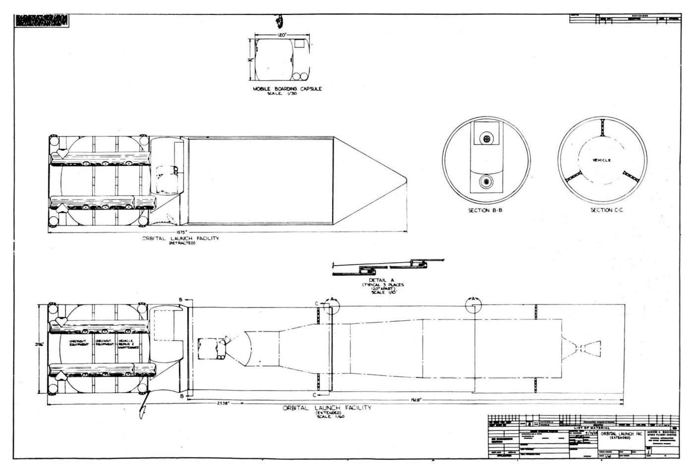
Preliminary design of spacecraft capable of undertaking early Venus and Mars round-trips based on the capabilities of the Saturn launch vehicle family.
Identification of launch vehicle requirements and comparison with current programs.
Development plan and funding schedule.

The method of approach was described in these terms:
By an iterative process, mission velocities, and their effects on booster and re-entry requirements, were compared with mission times and their effects on life support and environmental control weights for ‘nearly open’ and ‘nearly closed’ systems for different crew sizes. When it became clear that Earth departure velocity was the dominating factor for the missions under considerations, the analysis to select missions of minimum mass on Earth orbit was simplified to the selection of missions with minimum Barth departure velocities.

The many systems were investigated sufficiently to provide (within limits set by study fund limitations) an indication of applicability of the manned interplanetary program; development status; weight, size, and power characteristics; and cost. Vehicle concepts were developed and masses determined for different missions considering mission time and its effects on life support requirements, and also (with the influence of solar proximity) on shielding requirements. The spacecraft masses were compared with the velocity/payload performance capability of different Earth orbit boosters and the resulting combined weight effect for Earth surface launch boosters.

Principal assumptions developed for the EMPIRE study took account of a number of constraints. Among them:
The Earth surface launch vehicle was to be the Saturn V with the S-II serving as its second stage.
Systems carried to Earth orbit by the Saturn V were to rendezvous (where needed) to form the escape vehicle.
If possible, the mass required in Earth orbit was to be held to that achievable by two Saturn V launches (one rendezvous) so that a third launch pad could accommodate a backup launch vehicle and two payloads ready in the event either Saturn V launch were to fail.
The Earth orbit escape was to use a chemical propulsion system or a nuclear propulsion system developed from NERVA technology (either a single stage or a two stage configuration).
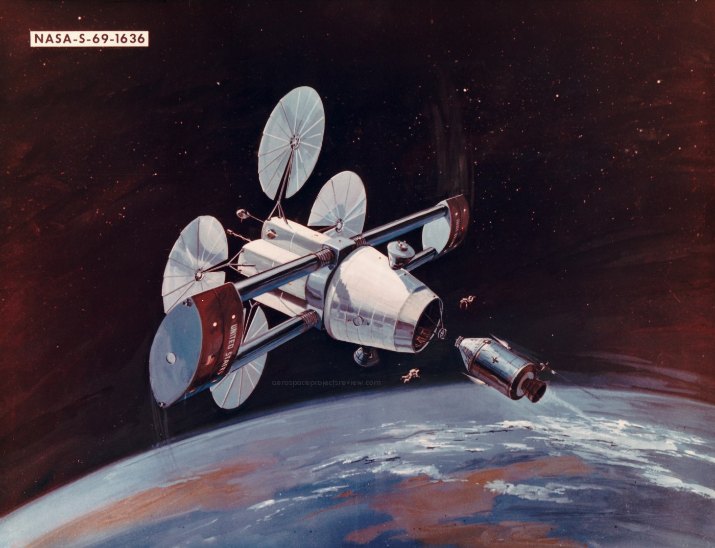
The spacecraft was to carry probes to gather direct data on planetary atmospheres and surface conditions.
Earth reentry was to be accomplished using an Apollo capsule modified to meet new mission requirements and increased entry speeds.
Unless and until it was established that an artificial gravity field was not required, vehicle systems capable of providing simulated gravity were to remain under investigation.

Study limitations were an important aspect of the LSMC effort. Considering the capability of the Saturn V, nuclear propulsion likely to be developed by then available technology, and the use of the Apollo spacecraft, the only interplanetary missions that appeared to be achievable were flybys. Limited funding precluded detailed investigations of the many subsystems such missions demanded.

LMSC made its first EMPIRE progress report on 6 August 1963 at the Marshall Center. A second report was delivered on 2 October 1963 at Lockheed’s Palo Alto, California, facility. It was concluded that launch vehicle and spacecraft performance and design assumptions were valid and that major subsystems had been more clearly identified and delineated than had earlier been the case.

At the conclusion of the study, the LMSC team under the direction of Benjamin P. Martin delivered its final report to the Marshall Space Flight Center in several volumes. The first of these was an unclassified summary of the complete study. The second volume consisted of unabridged findings in two parts, Part A containing all unclassified material and Part B incorporating classified data on the nuclear propulsion systems and their associated launch vehicles. The third volume was a condensed, unclassified summary of the entire project.”

The above is a brief extract from the ABSOLUTELY FANTASTIC, “save-the-day” content & imagery at the already superlatively informative ATOMIC ROCKETS website!!! With multiple diagrams - in which components are identified - SUPERB! With kudos & gratitude:

www.projectrho.com/public_html/rocket/realdesigns3.php#em...

See also:

www.astronautix.com/e/empirelockheed.html
Credit: Astronautix website

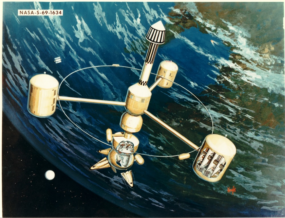
Per a September 30, 1963 press release caption associated with the photo:

“FOR FLYBY OF NEAREST PLANETS – Artist drawing of three-man spacecraft for flyby missions to Mars and Venus which will be discussed by Lockheed Missiles and Space Co., at meeting Monday on Engineering Problems of Manned Interplanetary Exploration in Palo Alto, Calif. The Apollo-type command module, upper right, houses crew during launch and serves as Earth re-entry vehicle. Living and recreation center below is 40 by 12 feet in diameter. Five-foot diameter spoke structure, 70 feet long, has central hub with power unit and mid-course propulsion unit.”

Meticulous artwork by Lockheed Missiles & Space Company artist Don Montello. I’ve seen a few works of his here & there.

~7.5” x 9”, poorly trimmed from possibly its original 8” x 10” by some well-intentioned yet misguided soul/dumb-ass.