The Flickr J2Engine Image Generatr

About

This page simply reformats the Flickr public Atom feed for purposes of finding inspiration through random exploration. These images are not being copied or stored in any way by this website, nor are any links to them or any metadata about them. All images are © their owners unless otherwise specified.

This site is a busybee project and is supported by the generosity of viewers like you.

AS-202_v_c_o_AKP (1966, Douglas Aircraft Co. photo no. D[A]C 19980) by Mike Acs

© Mike Acs, all rights reserved.

AS-202_v_c_o_AKP (1966, Douglas Aircraft Co. photo no. D[A]C 19980)

“Frequently used (mistakenly) as a Saturn V translunar injection (re: "In the Shadow of the Moon") this onboard piece is actually from a Saturn IB mission, AS-202. It is shot from the interstage forward of the S-I stage, facing forward, to document the separation of the S-IVB. Since no footage exists of a trans-lunar injection (where would it be shot from?) this is our best view of what an in-flight firing of the S-IVB looks like.”

The above is from the first linked video. The frame appears to be taken from the 15/16-second mark. Gorgeous:

vimeo.com/96999455
Credit: Pizza Marko

Two synched views, outstanding:

www.youtube.com/watch?v=PRu40PGQyTw
Credit: Retro Space HD/YouTube

Also…absolutely wonderful:

gwsbooks.blogspot.com/2015/04/camera-pods.html
Credit: Wes Oleszewski/“Growing Up With Spaceflight” website

a09_v_bw_o_n (Official NASA-MTF PAO photo, no. '68-236) by Mike Acs

© Mike Acs, all rights reserved.

a09_v_bw_o_n (Official NASA-MTF PAO photo, no. '68-236)

S-II-4 (Apollo 9), at the Mississippi Test Facility (MTF), is seen being prepared for its scheduled January 26, 1968 captive firing. In reality, the test, the first full-duration MTF captive rocket firing of 1968, was successfully completed on February 10. During it, the fourth flight version of the Apollo/Saturn V second stage was static fired for its full duration of six minutes.
The S-II-4 stage was the first of the so-called lightweight stages, being about 3,000 pounds lighter than the first three.
The structure on the right is the “S-II Vehicle Service Building”, bldg. no. 3203.

The above is paraphrased from the following, which is hopefully correct:

history.nasa.gov/MHR-5/part-9.htm

The fact that most everyone is wearing at least a lightweight jacket would seem to support this being S-II-4, and that the photograph was taken prior to static firing. I think.

Whatever it is, this is a strikingly sharp & bright photograph, of superior resolution…from 1968...impressive.

a_v_bw_o_n (S-63-72) by Mike Acs

© Mike Acs, all rights reserved.

a_v_bw_o_n (S-63-72)

Ca. 1962/63 North American Aviation (NAA) artist’s - I think Gary Meyer - concept depicting the Apollo spacecraft in earth/parking orbit, probably just before the Trans-Lunar Injection (TLI) burn by the S-IVB’s J-2 engine. The conduit-looking thing running along the side of the Service Module is actually one of the two “swing-arms” by which the Lunar Excursion Module (LEM) was to be rotated/pivoted from its stowed position behind the Command/Service Module (CSM) to the front of it for docking.
Although it would seem this method of “Transposition & Docking” removed the inherent risk/danger of having to precisely maneuver the CSM about multiple axes, it also introduced the potential of mechanical difficulty/failure of the swing-arms. Although I assume there was a contingency for disconnecting/jettisoning them (from the LEM) in the event of such. Fascinating - to me - regardless.

youtu.be/Qx2eXSCWJgE
Credit: The Space Archive/YouTube

youtu.be/GbNwBmRfTAw
Credit: Retro Space HD/YouTube

Who knew? Did you?!? I didn’t!!!

On the verso, I wonder what “…FROM NAA NUMBERS” means.

a01 (a05/AS-204)_v_c_o_AKP (107-KSC-67C-2094) by Mike Acs

© Mike Acs, all rights reserved.

a01 (a05/AS-204)_v_c_o_AKP (107-KSC-67C-2094)

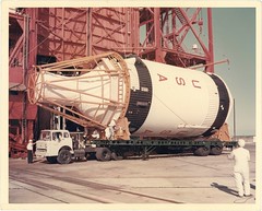
“AS-204, S-IVB de-erection on transfer trailer. Pad 34.
4-3-67”

“Compression” wrinkles in the central upper half of the image have fortunately, not broken the emulsion, and are barely visible when viewed head-on.

www.drewexmachina.com/2017/01/27/the-future-that-never-ca...

www.drewexmachina.com/2018/01/22/apollo-5-the-first-fligh...
Both above credit: Andrew LePage/Drew Ex Machina website

Everything, I mean EVERYTHING you ever wanted to know about the performance of this S-IVB stage is at the following link:

ntrs.nasa.gov/citations/19700026392

fut-spasta_v_bw_o_n (ca. 1968, unnumbered press/poss. Martin Marietta Corp. photo) by Mike Acs

© Mike Acs, all rights reserved.

fut-spasta_v_bw_o_n (ca. 1968, unnumbered press/poss. Martin Marietta Corp. photo)

“SPACE STATIONS AS TRAINING . . .”

…of/for what? Rock climbing? Repelling? Extravehicular Activity between spacecraft? Disabling Soviet spacecraft in orbit? 👍

Was there another companion work associated with this? To complete the caption? Or, was it a stand-alone work intended to spur the imagination, stir speculation, what?

I don’t even understand the combination of craft. By 1968, if the stamped date is correct, I think MORL was dead. And neither here nor there, but it looks more like MOL to me. Is this intended to represent an evolution of living and working in earth orbit? I’m really not tracking on this.

Who cares. What really matters is that it’s by John Gorsuch, therefore 👍👍👍.

aap-sl_v_c_o_AKP (NASA HQ MC 67-5004, 1-5-67) by Mike Acs

© Mike Acs, all rights reserved.

aap-sl_v_c_o_AKP (NASA HQ MC 67-5004, 1-5-67)

“APOLLO APPLICATIONS
EARTH RESOURCES EXPERIMENTS”

I’m not sure what’s going on here – there’s no Multiple Docking Adapter (MDA) – which I thought was a part of all (or so I thought) AAP configurations, even early ones. This depiction is of a direct CSM-to-workshop configuration. Along with that, there’s no evidence of there having been SLA panels that were jettisoned…to reveal whatever…like the MDA. Additionally, being 1967, this must be a ‘wet’ workshop, right? But with only the “earth resources experiments” section/compartment cut away? Also, oddly/interestingly, the cylinder (with hatch?), extending inward from the far wall I suppose is an/the airlock. Right? I think it’s way too big to be some sort of earth resources experiment package. Then again, who knows.

a_v_bw_o_n (62-Apollo-103) by Mike Acs

© Mike Acs, all rights reserved.

a_v_bw_o_n (62-Apollo-103)

“ARTIST CONCEPTION – The third stage of the C-5 Saturn configuration has burned for the second time, we have committed the mission to lunar trajectory. After injection and re-orienting the command module-service module so that we actually mate the command module-service module combination with the lunar excursion module the S-IVB is dropped away.”

It’s from 1962, so it’s still referred to as the C-5…outstanding. Although the brilliant depiction is of North American Aviation (NAA) origination, specifically, by the hand of the remarkably talented/gifted Gary Meyer, I’m not so sure about the caption. Unlike many of the early Apollo artist’s concepts, also by Mr. Meyer, NAA attribution has been removed. That may also include the original caption, which might account for the awkward & clunky wording & nomenclature, commensurate with a NASA origination.

A testament to Mr. Meyer’s talent & vision. This looks like a work based on events that had already transpired and had possibly been photographically captured. Again, it’s from 1962. U.S. astronauts had barely started to orbit the earth, in converted/man-rated missiles & only the first several Block I Saturns had been successfully test flown!

Wonderful. Rest In Peace Good Sir. Thank You:

garymeyerillustration.net/ILLUSTRATIONS/Pages/early_work....
Credit: GARY MEYER ILLUSTRATION website

aap-sl_v_bw_o_n (ca. 1968, unnumbered poss. press photo) by Mike Acs

© Mike Acs, all rights reserved.

aap-sl_v_bw_o_n (ca. 1968, unnumbered poss. press photo)

Delightfully “huh?”.

If the stamped date is correct/close, this looks to be an Apollo Applications Program (AAP) S-IVB “wet” workshop, sort of confirmed by the presence of the Rocketdyne J-2 engine.
If correctly identified, it really makes this a “huh”. If something other, like being one end of a larger rotating complex, that could conceivably account for the obvious presence of artificial gravity.

And, neither here nor there, but it looks like the work of John Gorsuch to me.

(Untitled) by Richard Par

© Richard Par, all rights reserved.

a_v_bw_o_n (MAF-MSFC photo, no. 12367 20, verso date stamped NOV 21 1966) by Mike Acs

© Mike Acs, all rights reserved.

a_v_bw_o_n (MAF-MSFC photo, no. 12367 20, verso date stamped NOV 21 1966)

“Three different rocket engines used to power the two Saturn vehicles are lined up at the National Aeronautics and Space Administration’s Michoud Assembly Facility. The Uprated Saturn I and Saturn V vehicles, the first stages of which are assembled at Michoud, are designed for use in Project Apollo, the United States’ manned lunar exploration program. The engines were built for NASA by the Rocketdyne Division of North American Aviation, Inc. Eight of the H-1 engines, (left) will develop 1.6 million pounds of thrust at liftoff for the Uprated Saturn I first stage. Five F-1 engines (center) will provide 7.5 million pounds of thrust for the Saturn V first stage. The J-2 engine (right) is used on both vehicles. Five J-2’s will give one million pounds of thrust to the second stage of the Saturn V and one J-2 will power both the third stage of the Saturn V and second stage of the Uprated Saturn I. The Uprated Saturn I will be used for astronaut training and testing the Apollo spacecraft’s systems, while the Saturn V will launch manned Apollo flights to the moon within this decade.”

Quite the lineup, eh?
FIFTY-FIVE (55)+ years ago!

Note that the F-1 does not have its nozzle extension attached.

Well-written, commensurate with the amazing quality, depth, richness & detail of the photograph.

Finally, too cool:

rocketreference.com/wp-content/uploads/2019/02/H-1-F-1-Co...
Credit: "ROCKETreference.com" website

STSprog/fut_v_c_o_AKP (NASA-S-71-4084-X) by Mike Acs

© Mike Acs, all rights reserved.

STSprog/fut_v_c_o_AKP (NASA-S-71-4084-X)

Further reinforcing my perpetual confusion of space shuttle concept identifications during the late 60’s - mid 70’s, there’s this.

I’m pretty sure this design is referred to as “MSC 040A”. Possibly during/under Phase-B’? - with not two, not three, but 4, count ‘em, FOUR main engines - AND bulging ‘canopy’.
Who knew?!
As if that wasn’t enough, I think subsequent(?) to this, design “MSC 042A“ featured ZERO main engines…sort of a pre-Buran Buran design. And, get this, riding atop an uprated Titan IIIL-6 (apparently with 6 strap-on SRBs).
I don’t even know what that is!

The information is out there, to a degree, in bits & pieces & all over the place. Unfortunately, it’s inducing exponentially increasing ass-pain finding/confirming accurate information.

Fortunately, in this instance:

“…Though the issue of payload size and weight was still open, the basic design of the orbiter was approaching a definitive form. During the fall of 1971, when the Mark I/Mark II approach was still in the forefront, the contractors had worked from a Max Faget configuration known as MSC-040A. It elaborated the earlier MSC-040 by adding small liquid-fuel engines for orbital maneuvers, along with thrusters for attitude control that were mounted at the tips of the wings and tail.

The Mark I/Mark II concept, however, with its phased technology, had never been more than an artificial stratagem to reduce peak funding by stretching out the development, while accepting serious compromises in design. With Shultz’s support, NASA now was free to build an honest orbiter, one that would be right the first time. MSC-040A had called for four J-2S engines; a variant of January 1972, MSC-040C, replaced them with three SSMEs…”

At:

history.nasa.gov/SP-4221/ch9.htm

Also, always excellent:

www.capcomespace.net/dossiers/espace_US/shuttle/index.htm

Specifically:

mirrors.josefsipek.net/www.capcomespace.net/dossiers/espa...
Credit: CAPCOM ESPACE website (mirror)

Finally, what’s most important, a beautiful work, unfortunately by an unidentified artist, wonderfully exemplifying the evolution of designs, as evidenced below. In this, I’m amused not only by the slightly undersized nozzle of the upper right engine, but also the detail of the aft bulkhead/base heat shield, where the engines are attached…nice.

UPDATE: Based on another work from this 'series', I believe this to be the work of Norman Tiller.

a_v_bw_o_n (1964, Boeing Co. photo no. P 35167) by Mike Acs

© Mike Acs, all rights reserved.

a_v_bw_o_n (1964, Boeing Co. photo no. P 35167)

“A possible use of the Boardman test site in north central Oregon might involve test of multi-stage rocket boosters. In this sketch, the connections between two booster stages are ruptured explosively during a test of the stage separation design. Tests also could involve the start of engines immediately after separation. For these tests, tied-down boosters would be fired in a horizontal position. Television camera at right would monitor tests.”

Wow, horizontal testing of Saturn V launch vehicle staging, with the possible firing of engines after such…DAMN. Who knew? Did you?! I didn’t!!!

Although I know squat about what actual Apollo/Saturn testing occurred at the Boardman test site, I’m pretty sure this was never conducted. It certainly would’ve been quite a sight, whether successful or not.
I find it odd that the launch vehicle depicted – obviously a Saturn V – is not specifically identified.

Finally, the S-II stage, seen igniting, is short an engine. Maybe from a Boeing perspective, since it was manufactured by NAA, the depiction was considered close enough. If so, that’s pretty arrogant. Unless, at this point, four engines were still under consideration? However, by 1964, I’d doubt it. Possibly portending the erosion of Boeing’s culture, competence & ethos.

Most importantly, per Mr. Paul Woods and his wonderful "MOONBASE CENTRAL" website, this dynamic & rarely seen work is by Boeing’s venerable & highly talented resident artist/illustrator, Warren McCallister:

projectswordtoys.blogspot.com/2013/09/birthday-5-warren-m...

a_v_bw_o_n (1966, unnumbered NAA photo) by Mike Acs

© Mike Acs, all rights reserved.

a_v_bw_o_n (1966, unnumbered NAA photo)

1966 North American Aviation (NAA) artist’s concept of the CSM/S-IVB stack either shortly before, or shortly after, Trans-Lunar Injection (TLI). Most likely – I think – by Gary Meyer.

sl3,ASTPbu_v_c_o_AKP (ca. 1967, official Douglas Aircraft Co. photo G83-202) by Mike Acs

© Mike Acs, all rights reserved.

sl3,ASTPbu_v_c_o_AKP (ca. 1967, official Douglas Aircraft Co. photo G83-202)

“Stage 208 (foreground) on cradle and Stage 209 (in background) on the Low Profile Dolly inside the Manufacturing Services Building.”

If to be believed, the following, for July 1967:

“NASA began the last half of 1967 with Saturn IB stages for AS-205, AS-206, and AS-208 in storage. AS-209 was in various stages of development. For example, post-static checkout of S-IB-9 and also S-IVB-209 was continuing. The S-IVB-209 stage had undergone a successful static firing the previous month, on June 20, as scheduled for a mainstage duration of approximately 456 seconds. S-IU-209 assembly previously scheduled for completion on June 26 was delayed to July 10 because of shortage of assembly supplies, including lack of some distributors. At this same time the later Saturn IB vehicle, AS-210, was under development. S-IB-10 was undergoing post-static modification and repair. S-IVB-210 was in storage at Huntington Beach awaiting availability of Beta 3 test stand at SACTO. Fabrication of S-IU-210 had been completed June 21, 1967, and assembly operations were in process.”

At:

history.nasa.gov/MHR-5/part-8.htm

With the image at:

history.nasa.gov/MHR-5/Images/fig369.jpg

And the caption of:

“S-IVB's in storage at SACTO”

a_v_c_o_AKP (116-KSC-66C-1806) by Mike Acs

© Mike Acs, all rights reserved.

a_v_c_o_AKP (116-KSC-66C-1806)

“Artist concept of “Moon Mission”.”

Well…I suppose it’s better to have a kick-ass artist’s concept paired with a underwhelming caption, than the other way around, right? The stunning work depicts the separation of the S-IVB stage from the spent S-II stage of the Saturn V launch vehicle. Note the four retro rockets firing in order to ensure safe separation of the two stages.

I’m certain by the incredibly talented Gary Meyer. See his depiction of the same event, I believe three years earlier, at:

garymeyerillustration.net/ILLUSTRATIONS/Pages/early_work....
Credit: “GARY MEYER ILLUSTRATION” website

a04_v_bw_o_n (no. 1, 1967, S-IVB ascent) by Mike Acs

© Mike Acs, all rights reserved.

a04_v_bw_o_n (no. 1, 1967, S-IVB ascent)

Based on the date stamped on the verso, the day after the flight/mission, the vehicle is likely Apollo 4, depicted during ascent, propelled by the single J-2 engine of the S-IVB stage.

Stylistically, and with the often-recurring numbering in the corner of the photo, this is likely another lost/forgotten? gem by Russell Arasmith. Although a slightly less polished, less detailed effort when compared to latter renderings. Possibly due to being early/earlier during Mr. Arasmith’s incredible career? And combined with maybe less available imagery to work with, this being the first launch of the Saturn V rocket.
Obviously one of a series, although a little odd that this phase of the flight would be labeled no. 1. I just need to ‘shut up’ & not look a gift-horse in the mouth…this is a win.

A full life:

www.dignitymemorial.com/obituaries/westminster-ca/russell...
Credit: Dignity Memorial website

I'm sure only a fraction:

www.nasa.gov/centers/marshall/history/arasmith-gallery.html

A wonderful peak, confirming my above statement:

d3eguztg5751m.cloudfront.net/as/assets-mem-com/cmi/7/7/9/...
Credit: The Arasmith Family/Dignity Memorial website

a07_v_bw_o_n (no. 4, ca. 1968, rendezvous) by Mike Acs

© Mike Acs, all rights reserved.

a07_v_bw_o_n (no. 4, ca. 1968, rendezvous)

“This drawing, looking over the shoulder of command pilot Walter Schirra, shows approach of the Apollo 7 module and its third stage booster in rendezvous exercise. Sighting device is lighted reticle projected on window by instrument above.”

The 'instrument' is the Crewman Optical Alignment Sight (COAS). Interestingly, very little is available, both in images & text, pertaining to the one used within the Command Module. Understandably, the analogous COAS used inside the Lunar Module is by far more 'popular'.

history.nasa.gov/afj/ap13fj/pics/coas-diagram.jpg
Credit: Apollo Flight Journal website

Despite being really into Apollo photos, I'm not all that familiar with the CM's instrument panel(s), however; the depiction appears to be pseudo-accurate, albeit greatly simplified.

7.75" x 9.375".

Fortunately, yet another unique, creative & unexpected Arasmith find.

A full life:

www.dignitymemorial.com/obituaries/westminster-ca/russell...
Credit: Dignity Memorial website

Thank You Sir, Continue to Rest In Peace.

a07_v_bw_o_n (no. 5, ca. 1967/68, montage) by Mike Acs

© Mike Acs, all rights reserved.

a07_v_bw_o_n (no. 5, ca. 1967/68, montage)

A striking & very original/unique (in choice of scenes) ca. 1967 montage by the eminently talented/prolific Russell Arasmith, possibly as part of press coverage preceding the flight of Apollo 7.
Note the faintly outlined blank rectangular area to the lower right. Possibly for whatever descriptive text to be inserted by press organizations, such as crew, launch date, spacecraft details, etc., etc.
Understandably, the CSM & spacesuit configuration/appearance is based on Apollo 1. The Rocketdyne J-2 engine of the S-IVB stage figures prominently in the illustration as well.

The discovery of rare, seldom/never seen ‘space’ artwork, such as this, is sadly, always tempered in knowing that there’s so much more that will never see the light of day again.

As is often the case with Mr. Arasmith’s works, numbering is seen in the corner of the border. Probably identifying its sequence in a/the series.
See what I mean? There were then four preceding this one, and who knows how many after it! Most, likely gone.

A full life:

www.dignitymemorial.com/obituaries/westminster-ca/russell...
Credit: Dignity Memorial website

aap-sl_v_bw_o_n (ca. ~1965-67 unnumbered prob. Douglas Aircraft Co. photo, NASA HQ MC68-5689 eq) by Mike Acs

© Mike Acs, all rights reserved.

aap-sl_v_bw_o_n (ca. ~1965-67 unnumbered prob. Douglas Aircraft Co. photo, NASA HQ MC68-5689 eq)

“SPACE WORKSHOP – Possible first phase of the Saturn S-IVB Orbital Workshop concept by Douglas Aircraft Company artist shows how giant rocket will appear after it is converted into two-story experimental laboratory in the National Aeronautics and Space Administration’s Apollo Applications Program. The S-IVB stage (right) will be launched fully fueled, carrying the docking adapter and airlock seen in center. These will give astronauts access to the rocket’s liquid hydrogen tank after propellants have been depleted and will provide a “shirtsleeve” environment inside. Astronauts will be launched separately in an Apollo vehicle, rendezvous with the S-IVB and dock as shown at left. Cutaway section of S-IVB shows floor and partitions of lightweight metal grating which will divide the tank into separate “rooms” for astronaut activities without interfering with flow of fuel during launch. The “wings,” panels of solar cells to provide electric power, are folded down against the S-IVB during launch and extended after orbit is achieved.
A windmill-like structure, the Apollo Telescope Mount, will be mounted against the side of the docking adapter, and will be added to the Workshop in the second phase of the program. Douglas, a component of McDonnell Douglas Corporation, builds the S-IVB at its Missile & Space Systems Division, Huntington Beach, Calif., for NASA’s Marshall Space Flight Center and is making necessary modifications to the Orbiting Workshop vehicle under MSFC direction. The airlock is being developed by the McDonnell Astronautics Company, St. Louis, Mo., under contract to NASA’s Manned Spacecraft Center.”

The astronauts are wearing hard hats in this version, but not in the linked image. Possibly concluded that nothing was going to "fall" and hit them in the head while in orbit. However, reckless floating is another matter. 😉

The above is paraphrased from a Douglas Aircraft Co. write-up associated with the “Phase 2” depiction of the workshop, also rendered by Neil Jacobe, and linked below.

As with space shuttle concepts of the late 1960s - early 1970’s, there seemed to have been no shortage of concepts - submitted by multiple contractors - for Apollo Applications Program (AAP) concepts and eventual Skylab configurations. So, I have no idea what the correct date of this photo is. I really doubt it’s 1970, as stamped on the observe, that just being when this particular newspaper pulled it out to publish. September 24, 1970 was probably a slow news day.

The accompanying press slug nonetheless merits regurgitating, especially the stinging last sentence.
Just one of many reasons that the relatively simple feat, by the United States manned space flight program…SpaceX actually…of sending two guys into low earth orbit was/is such a big deal - IN THE YEAR 2020 - after nine years of...nothing. Learning to walk again after misdiagnosed, prolonged & self-imposed bed rest:

“Called “SKYLAB,” this pioneering space observatory and workshop, scheduled to be launched in 1972, will provide living and working space for astronauts orbiting earth on missions as long as 56 days.
It is the only new project in space being financed by the U. S.”

a10_v_bw_o_n (no. 1, 1969 Arasmith concept, rend & dock, extrct, TLI) by Mike Acs

© Mike Acs, all rights reserved.

a10_v_bw_o_n (no. 1, 1969 Arasmith concept, rend & dock, extrct, TLI)

“FOUR-STEP sequence shows Apollo 10 mission leaving earth orbit for translunar voyage. At left, third stage of Saturn 5 launch rocket burns for second time to ram spacecraft out of earth orbit. Then command, service modules separate, panels fly clear to disclose Lunar Module (LEM) at top of stage. Now command ship docks with Lunar Module, combined spacecraft separates from rocket stage. After combined spacecraft turns toward moon, service rocket burns to complete separation maneuver.”

Surely by Russell Arasmith. The following pretty much confirms. Beautiful...both

www.nasa.gov/centers/marshall/history/russ-arasmith-apoll...