The Flickr Mappingthemoon Image Generatr

About

This page simply reformats the Flickr public Atom feed for purposes of finding inspiration through random exploration. These images are not being copied or stored in any way by this website, nor are any links to them or any metadata about them. All images are © their owners unless otherwise specified.

This site is a busybee project and is supported by the generosity of viewers like you.

LO I_v_bw_o_n (ca. 1966, Boeing photo no. H31969) by Mike Acs

© Mike Acs, all rights reserved.

LO I_v_bw_o_n (ca. 1966, Boeing photo no. H31969)

“This photo of a bulletin board shows some of the clippings taken from leading U. S. newspapers during and shortly after the Lunar Orbiter I mission. Stories of the mission were given prominent play in such leading publications as the Los Angeles Times, The New York Times, Christian Science Monitor, the Los Angeles Herald Examiner, the Pasadena Independent, Life magazine, Time and Newsweek magazines.”

The bulletin board was likely at Boeing’s Seattle, Washington headquarters.

LO I_o (66-H-1380) by Mike Acs

© Mike Acs, all rights reserved.

LO I_o (66-H-1380)

“The world’s first view of the Earth taken by a spacecraft from the vicinity of the Moon. The photo was transmitted to Earth by the United States Lunar Orbiter 1 and received at the NASA tracking station at Robledo De Chavela near Madrid, Spain. This crescent of the Earth was photographed August 23, at 16:35 GMT when the spacecraft was on its 16th orbit and just about to pass behind the Moon. This is the view the astronauts will have when they come around the backside of the moon and face the Earth. The Earth is shown on the left of the Photo with the U.S. east coast in the upper left, southern Europe toward the dark or night side of Earth, and Antarctica at the bottom of Earth crescent. The surface of the Moon is shown on the right side of the photo. Re-enhanced photograph - October 24, 1966.”

This photo is part of the historic & iconic ‘first photo of Earth from the moon’ panorama, comprising the middle ~third of it. The first photograph linked to below is NASA photo ID no. 66-H-1379, it being the right/upper (depending upon orientation) ~third of that panorama. Could that mean there’s a 66-H-1381…it being the left/lower ~third? I doubt it, that would be logical/make too much sense.

The conspicuous ‘dark’ crater to the right is Khvol’son. Hilbert E is at the lower right of the image. A portion of Hilbert Crater & its multiple other satellite craters are spread across the surface to the left of Hilbert E.

See also:

www.lpi.usra.edu/resources/lunarorbiter/frame/?1102

Specifically:

www.lpi.usra.edu/resources/lunarorbiter/images/preview/11...
Both above credit: LPI website

LOprog_v_bw_o_n (67-H-149, Boeing photo no. P39283 eq) by Mike Acs

© Mike Acs, all rights reserved.

LOprog_v_bw_o_n (67-H-149, Boeing photo no. P39283 eq)

“A camera-carrying Lunar Orbiter spacecraft spreads antennas and winged solar panels as it settles into the black maw of a 50-foot-high space environment chamber at the Boeing Space Center near Seattle, Washington. For the next three weeks it will undergo flight acceptance tests during a simulated photographic mission to the moon. The real-time simulation will include camera operation and readout. To simulate conditions in space, the chamber will be sealed and pumped down to a vacuum equivalent to about 100 miles altitude. The spacecraft will be subjected to temperature extremes expected during a translunar journey and at least nine orbits around the moon Each orbit will take slightly more than three hours and the temperature will vary from about minus 300 degrees Fahrenheit on the dark side of the moon to plus 250 degrees Fahrenheit on the sunny side. This is the first ground-test Lunar Orbiter to undergo a mission simulation under space environment conditions. The Lunar Orbiter program is managed by the National Aeronautics and Space Administration’s Langley Research Center. Boeing is building eight Lunar Orbiters for NASA--five flight models and three ground test vehicles. The first launch is scheduled for mid-1966.”

See also, erroneously referred to as Lunar Orbiter 1 in the heading:

moonviews.com/?p=11

LOprog_v_bw_o_n (L-67-5651) by Mike Acs

© Mike Acs, all rights reserved.

LOprog_v_bw_o_n (L-67-5651)

Where the magic happened.

Tim Samshuijzen’s wonderful Lunar Orbiter camera photos (linked to below) and their accompanying Eastman Kodak descriptions, allowed me to compile/paraphrase the following:

“The Kodak photographic subsystem of the Lunar Orbiter contained two cameras, a film processor, and a readout system. The entire unit was contained in a shell of aluminum .015 or 1/64th of an inch thick and measuring 22 x 26 x 32 inches. The pressure, temperature, and humidity in the shell were controlled. Total weight was about 145 pounds. The film, film advance, and shutter control were common to both cameras. A special sensor in the photo subsystem tracked the lunar surface through the 24-inch lens and determined the proper compensation for the movement of the spacecraft relative to the lunar surface.

The two lenses in the two lunar orbiter cameras simultaneously made high- and medium-resolution exposures. The large lens (left), a 24-inch Paxoramic lens manufactured by Pacific Optical Company, produced the high-resolution photos of approximately 3-foot or 1-meter ground resolution. The smaller (right) 80mm Schneider wide-angle lens made the medium-resolution exposures of approximately 8-meter ground resolution. In one photographic pass over the moon’s surface, the Kodak photo subsystem exposed up to 20 frames of two pictures each. The intervals between frames varied from 2.2 to 8.8 seconds. The slow, high-resolution Kodak High-Definition Aerial film, used in the lunar orbiter camera, required long exposures. The film was 70mm wide, the same width as 120 amateur film, with a resolution of 450 lines per millimeter for a potential capability of 29,250 lines for the width of the film used. The optical-mechanical scanner in the subsystem scanned 18,942 lines over the 2¼” width of film. Prior analysis of the lunar surface, based on photographs from the Earth, was used to determine the exposure time. At least 176 frames of two pictures each were exposed with enough extra film footage to provide a potential of about 215 frames. When exposing a picture, the camera unit automatically (1) activated the movement-compensating sensor, (2) clamped the film to the platens and flattened it, and (3) opened the shutters to make two exposures simultaneously. The exposed film was stored on a looper system to await processing at times other than during actual photography or during the lunar night. Nine photographic targets of potential Apollo landing sites were recorded before the film supply was exhausted.

The Kodak photo subsystem processed the film before scanning into the video relay to the ground. The drum, (on the far left) contained the Kodak Bimat film supply. A gelatin layer on this film was saturated with a photographic processing solution. The Bimat film was laminated with the camera film on the small drum in the center where it developed and fixed the film in about 3½ minutes. The Bimat film then left the camera film and passed onto a separate take-up reel (on the right with the spokes). The camera film then passed over the drying drum at the bottom (barely visible above the lip of the shell). At a temperature of 95° F on the drum dried the film in about 11½ minutes. It then moved to the readout system.”

Amazing.

Additionally:

www.drewexmachina.com/2017/08/01/lunar-orbiter-5-filling-...
Credit: Andrew LePage/Drew Ex Machina website

LO I_o (66-H-1379) by Mike Acs

© Mike Acs, all rights reserved.

LO I_o (66-H-1379)

“The world’s first view of the Earth taken by a spacecraft from the vicinity of the Moon. The photo was transmitted to Earth by the United States Lunar Orbiter 1 and received at the NASA tracking station at Robledo De Chavela near Madrid, Spain. This crescent of the Earth was photographed August 23, at 16:35 GMT when the spacecraft was on its 16th orbit and just about to pass behind the Moon. This is the view the astronauts will have when they come around the backside of the moon and face the Earth. Re-enhanced photograph- October 24, 1966.”

Although this photo is part of the commonly seen panorama, this is actually the right/upper (depending upon orientation) ~third of that panorama…no earth. But hey, it’s a NASA caption, it is what it is.

See:

www.lpi.usra.edu/resources/lunarorbiter/frame/?1102

Specifically:

www.lpi.usra.edu/resources/lunarorbiter/images/preview/11...
Both above credit: LPI website

LOprog_vr_bw_o_n (L-66-1571) by Mike Acs

© Mike Acs, all rights reserved.

LOprog_vr_bw_o_n (L-66-1571)

“20TH ANNIVERSARY OF THE APOLLO 11 LUNAR LANDING

MAPPING THE MOON – The surface of the moon’s equatorial region was photographically mapped during the Lunar Orbiter Mission. The maps, which were compiled at Langley Research Center, provided the detailed topographical information needed to pinpoint the best landing sites, including the exact spot in the Sea of Tranquility chosen for Apollo 11.”

Although the presence/placement of the photo ID number, along with the yellowing of the photo paper would suggest it being original/vintage, it’s high gloss surface is basically flawless, so maybe it is ca. 1986…although the “20TH” is crossed out on the attached caption. IDK.

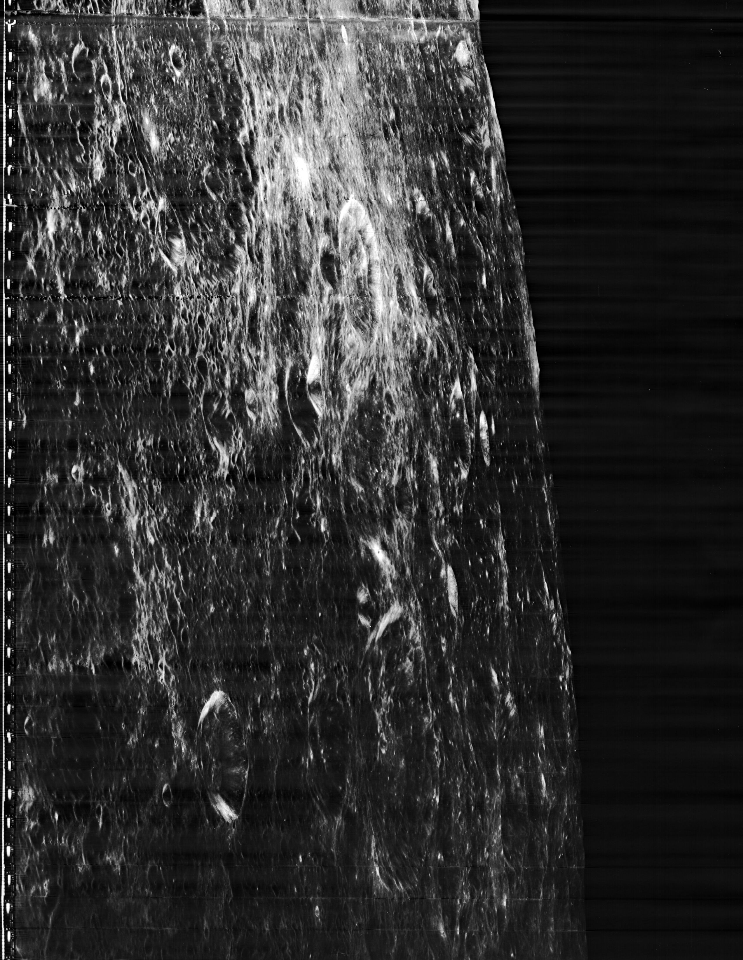
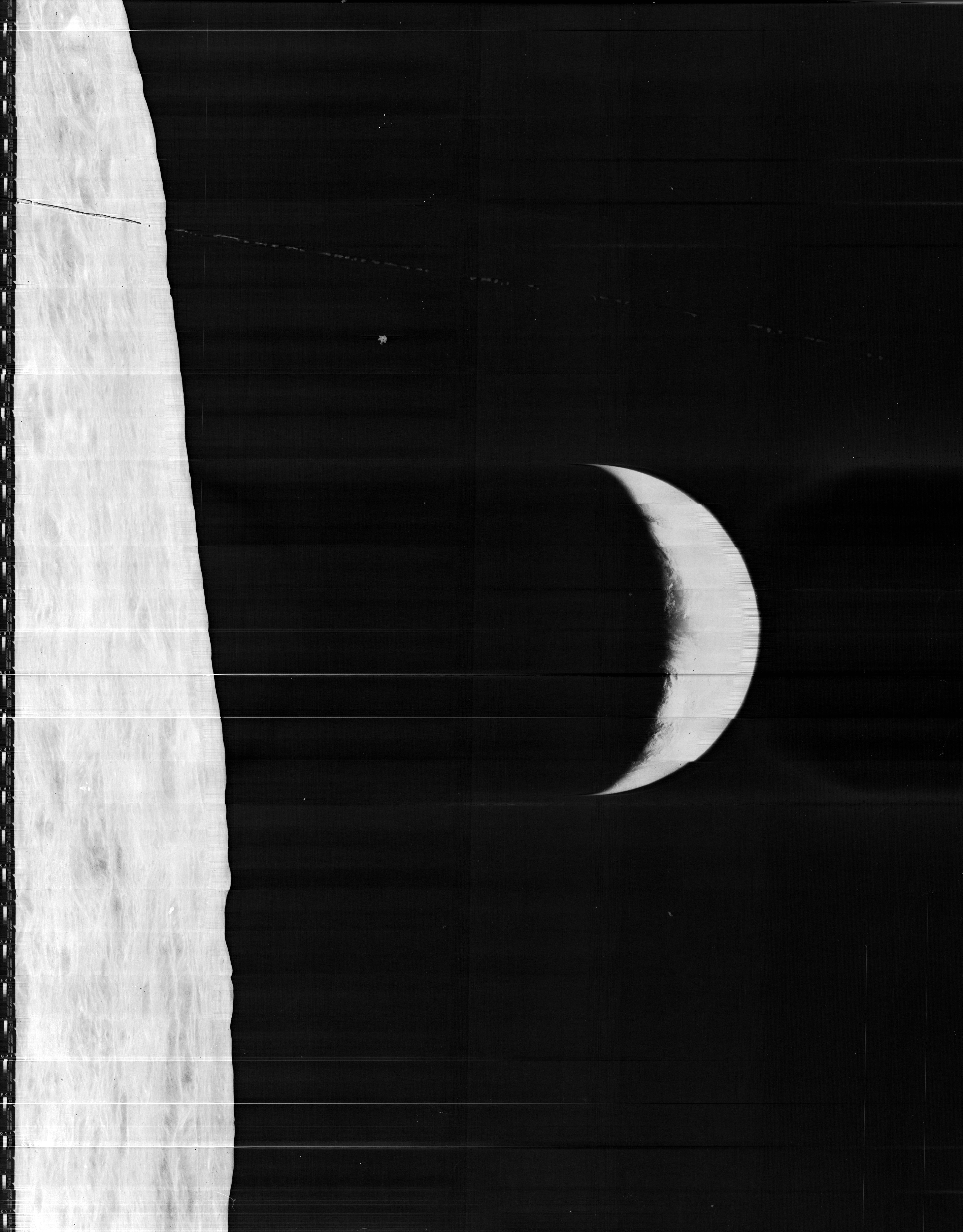
I’ve been familiar with this photo for as long as I can remember, and identified it early on as being an actual photograph…of a Lunar Orbiter model…positioned over a physical simulated lunar surface. I recognized the distinctive airbrushed surface, also for as long as I can remember, as being associated with simulating orbiting/landing on the moon. Life, family, career, etc., etc. got in the way of pointlessly piecing it together…until now…since I no longer have much of a life. So, what we’re looking at, other than the possibly suspended? Lunar Orbiter model, is:

“Project LOLA or Lunar Orbit and Landing Approach was a simulator built at Langley to study problems related to landing on the lunar surface. It was a complex project that cost nearly 2 million dollars. James Hansen wrote: "This simulator was designed to provide a pilot with a detailed visual encounter with the lunar surface; the machine consisted primarily of a cockpit, a closed-circuit TV system, and four large murals or scale models representing portions of the lunar surface as seen from various altitudes. The pilot in the cockpit moved along a track past these murals which would accustom him to the visual cues for controlling a spacecraft in the vicinity of the moon. Unfortunately, such a simulation--although great fun and quite aesthetic--was not helpful because flight in lunar orbit posed no special problems other than the rendezvous with the LEM, which the device did not simulate. Not long after the end of Apollo, the expensive machine was dismantled." (p. 379)
Ellis J. White further described this simulator in his paper, "Discussion of Three Typical Langley Research Center Simulation Programs," (Paper presented at the Eastern Simulation Council (EAI's Princeton Computation Center), Princeton, NJ, October 20, 1966.) "A typical mission would start with the first cart positioned on model 1 for the translunar approach and orbit establishment. After starting the descent, the second cart is readied on model 2 and, at the proper time, when superposition occurs, the pilot's scene is switched from model 1 to model 2. then cart 1 is moved to and readied on model 3. The procedure continues until an altitude of 150 feet is obtained. The cabin of the LM vehicle has four windows which represent a 45-degree field of view. The projection screens in front of each window represent 65 degrees which allows limited head motion before the edges of the display can be seen. The lunar scene is presented to the pilot by rear projection on the screens with four Schmidt television projectors. The attitude orientation of the vehicle is represented by changing the lunar scene through the portholes determined by the scan pattern of four orthicons. The stars are front projected onto the upper three screens with a four-axis starfield generation (starball) mounted over the cabin and there is a separate starball for the low window." -- Published in James R. Hansen, Spaceflight Revolution: NASA Langley Research Center From Sputnik to Apollo, (Washington: NASA, 1995), p. 379.”

Above at/per:

artsandculture.google.com/asset/project-lola-or-lunar-orb...
Credit: Google Arts & Culture website…and I’m sure others

Also:

“…Fifty-four years ago, we tested out Project LOLA—the Lunar Orbit and Landing Approach simulator—at the Langley Research Center in Virginia. The pilot perched on a gantry, peeking out the cockpit at a close-circuit TV system that tracked along detailed lunar mosaics in response to their commands.

NASA constructed four models at different scales, so the cockpit could track over the murals simulating a landing. The largest was on a six-meter (20-foot) diameter sphere, simulating the lunar surface from an altitude of 322 kilometers (200 miles) so every 1 centimeter covered 5.7 kilometers (1 inch per 9 miles). The three smaller full-relief scaled sections at 4.5 meter (15 feet) by 12 meter (40 feet). The final model of Crater Alphonsus scaled to just 1 centimeter for every 61 meters (1 inch to 200 feet). The lunar surfaces were created by carefully hand-painting and airbrushing the surfaces using detailed photographs taken from earlier lunar missions.

A typical test run lasted an hour with the pilot in the cockpit controlling how the television cameras tracked along the models. The mission started with the cart positioned on Model 1, establishing the translunar approach and orbit. During descent, the television feed switched to a second camera on Model 2 while the first camera was shuffled over to Model 3. The simulation cut out around a hundred meters (few hundred feet) from the “surface” to prevent the camera from bumping against the models.

The lunar module cabin allowed a 45° field of view over four windows; the simulator’s projection screens covered a broader 65° field of view. The lunar surface was rear projected using four Schmidt television projectors. Anywhere not covered by the “lunar surface” was a starfield created by front-projecting a four-axis starfield generator (starball) mounted above the cabin.

This is what the view looked like to the astronauts using the Project LOLA simulator:

youtu.be/gXOHeGpVkos
Credit: YouTube

A pair of Langley employees theorized that computer-controlled navigation would be insufficient to land on the moon, so they advocated for this $2 million dollar simulator. It was intended to familiarize astronauts with the alien surface, hopefully helping them identify visual cues that would let them aid the programs.

Apollo astronauts started using the simulator in 1964, but after the first moon landings they realized it wasn’t actually necessary. The simulator was soon decommissioned, and removed entirely by 1978.”

Above at/per:

gizmodo.com/project-lola-is-a-bizarre-snapshot-from-the-h...
Credit: Gizmodo website

Finally:

“Artists used paintbrushes and airbrushes to recreate the lunar surface on each of the four models comprising the LOLA simulator. Project LOLA or Lunar Orbit and Landing Approach was a simulator built at Langley to study problems related to landing on the lunar surface. It was a complex project that cost nearly $2 million dollars. James Hansen wrote: "This simulator was designed to provide a pilot with a detailed visual encounter with the lunar surface; the machine consisted primarily of a cockpit, a closed-circuit TV system, and four large murals or scale models representing portions of the lunar surface as seen from various altitudes. The pilot in the cockpit moved along a track past these murals which would accustom him to the visual cues for controlling a spacecraft in the vicinity of the moon. Unfortunately, such a simulation--although great fun and quite aesthetic--was not helpful because flight in lunar orbit posed no special problems other than the rendezvous with the LEM, which the device did not simulate. Not long after the end of Apollo, the expensive machine was dismantled." (p. 379) Ellis J. White further described LOLA in his paper "Discussion of Three Typical Langley Research Center Simulation Programs," "Model 1 is a 20-foot-diameter sphere mounted on a rotating base and is scaled 1 in. = 9 miles. Models 2,3, and 4 are approximately 15x40 feet scaled sections of model 1. Model 4 is a scaled-up section of the Crater Alphonsus and the scale is 1 in. = 200 feet. All models are in full relief except the sphere." Published in James R. Hansen, Spaceflight Revolution: NASA Langley Research Center From Sputnik to Apollo, (Washington: NASA, 1995), p. 379; From Ellis J. White, "Discussion of Three Typical Langley Research Center Simulation Programs," Paper presented at the Eastern Simulation Council (EAI's Princeton Computation Center), Princeton, NJ, October 20, 1966.”

Above at/per:

www.dvidshub.net/image/696114/apollo-project
Credit: Defense Visual Information Distribution Service (DVIDS) website

In conclusion & based on the above (and a couple of the linked photos below), I think this is Model 2. Although the prominent crater in the lower right foreground is Alphonsus, I don’t think its scale is sufficient to be Model 4…the scaled-up section of Alphonsus. For orientation, the other conspicuous crater, with the dark-ringed floor above Alphonsus & adjacent to the right border, is Albategnius. Further, the display of the lunar surface is not only reversed left-to-right, it’s inverted as well! For the purposes of rear projection, I understand the l – r reversal, but not the inversion. I’ve oriented the photo as it would’ve appeared as if standing in front of it, which nicely correlates with the first photo linked to below, which is also etched in my memory. Note that many of the same landmarks are visible.

With 20/20 hindsight it’s easy to question why NASA/Langley leadership proceeded with Project LOLA based on the idea on the ‘good idea’ of two guys. Although, it would seem to be self-evident that there wasn’t anywhere near enough resolution – in these otherwise beautiful works of art – to aid/train in landing on the moon. Maybe to commence an approach/initial descent, but I’d think that would’ve been it. And no provision for a rendezvous in orbit. I’ve never even read any Astronaut’s mention or review of LOLA. It would seem to have been a noble yet ‘not quite’ endeavor, albeit a showcase of artists’ airbrush prowess & precision, along with providing a $2M backdrop for a Lunar Orbiter press/promotional photo.

Addendum & nit-picking follow: Despite being an article touting Langley’s contributions to Apollo, you’d think someone should’ve known - if anyone knew/cared, that is – everything I’ve drolled on about above, or at least that this is obviously not an artist’s rendering:

“Pictured here is an artist rendering of the Lunar Orbiter Mission. The surface of the moon's equatorial region was photographically mapped during the Lunar Orbiter missions. The maps, compiled at Langley Research Center, provided the detailed topographical information needed to pinpoint the best landing sites.”

At:

www.nasa.gov/feature/langley/the-first-step-langleys-cont...

“Illustration of Lunar Orbiter in Flight
Concept art of Lunar Orbiter spacecraft in orbit around the Moon.”

At:

airandspace.si.edu/multimedia-gallery/5325hjpg

Also at:

www.nasa.gov/centers/langley/home/Road2Apollo-09.html

Finally, it’s plate [314] here:

history.nasa.gov/SP-4308/ch10.htm

history.nasa.gov/SP-4308/p314a.jpg

LO I_o (66-H-1146, L-66-6591 eq) by Mike Acs

© Mike Acs, all rights reserved.

LO I_o (66-H-1146, L-66-6591 eq)

“Washington, D.C., -- The world’s first view of the Earth taken by a spacecraft from the vicinity of the Moon. The photo was transmitted to Earth by the United States Lunar Orbiter I and received at the NASA tracking station at Robledo de Chavela near Madrid, Spain. This crescent of the Earth was photographed August 23, at 16:35 GMT when the spacecraft was on its 16th orbit and just about to pass behind the Moon. This is the view the astronauts will have when they come around the backside of the Moon and face the Earth. The Earth is shown on the left of the photo with the U.S. east coast in the upper left, southern Europe toward the dark or night side of Earth, and Antarctica at the bottom of Earth crescent. The surface of the Moon is shown on the right side of the photo.”

www.space.com/12707-earth-photo-moon-nasa-lunar-orbiter-1...
Credit: Space.com website

nssdc.gsfc.nasa.gov/imgcat/html/object_page/lo1_h102_123....

Also…really cool:

www.planetary.org/explore/space-topics/earth/pics-of-eart...
Credit: The Planetary Society website

And I'm sure plenty of others.

LO III_v_bw_o_n (ca. 1966-67, unnumbered press & poss. NASA photo) by Mike Acs

© Mike Acs, all rights reserved.

LO III_v_bw_o_n (ca. 1966-67, unnumbered press & poss. NASA photo)

“SKETCH III:
One of primary targets for Lunar Orbiter photo craft will be site where Surveyor I soft-landed on the moon to return more than 11,000 pictures from the lunar surface. Surveyor’s flat-faced solar panel and high-gain antenna have been positioned to the largest possible shadow to aid in catching Lunar Orbiter’s photographic eye. Photographs taken by Lunar Orbiter as low as 28 miles will permit precise study of terrain surrounding Surveyor site, as well as eight other proposed manned landing sites lying along lunar equator.
LOS ANGELES TIMES SYNDICATE”

Gorgeous. Russ Arasmith.

The same image:

www.nasa.gov/centers/marshall/history/russ-arasmith-apoll...

Two others:

www.nasa.gov/centers/marshall/history/russ-arasmith-lunar...

www.nasa.gov/centers/marshall/history/russ-arasmith-lunar...

LO I_o (66-H-1174, Frame 117, H2 eq) by Mike Acs

© Mike Acs, all rights reserved.

LO I_o (66-H-1174, Frame 117, H2 eq)

“The second view of the Earth taken by the National Aeronautics and Space Administration’s Lunar Orbiter I spacecraft. The view of the crescent Earth was made about midnight EDT, on August 24, when the spacecraft was in its 27th photographic orbit of the Moon. As the photograph was made, the spacecraft was just about to disappear behind the eastern edge of the Moon. The picture was received at NASA’s Woomera, Australia, tracking station during final readout of the Lunar Orbiter photography. The Earth appears on the left in this photograph. Much of the Earth’s crescent is clouded, covering the Antarctic continent near the bottom and areas of the Indian Ocean above. Lunar Orbiter is a project of NASA’s Langley Research Center, Hampton, Virginia.”

Although a wonderful & genuinely rarely seen image, let alone in actual physical form, the following, at what I consider to be THE authoritative source – reveals it to be left-to-right reversed:

www.lpi.usra.edu/resources/lunarorbiter/frame/?1117

Specifically:

www.lpi.usra.edu/resources/lunarorbiter/images/print/1117...

YOU’RE…
FU**ING…
KIDDING…
ME ? ! ♾

ALTHOUGH, I can almost understand this one - ALMOST - no readily identifiable features, on either body. But then again, would a NASA photographic “professional” have been able to say, identify major continental masses if such were discernable??? Probably NOT.

BOTTOM LINE: INFURIATING. It is still INEXCUSABLE…AND ARROGANT…BUFFOONERY…dating back to 1966 and persisting to this day.

Lunar Orbiter 4 by Mars, The Moon & More

© Mars, The Moon & More, all rights reserved.

Lunar Orbiter 4

Frame(s)
4193 h1
4193 h2
4193 h3

Rough stitching by hand in Photoshop CC

Contrast and colour adjusted in Photoshop CC

Lroc - Crookes Crater & Central Mounds (NAC Mosaic B) by Mars, The Moon & More

© Mars, The Moon & More, all rights reserved.

Lroc - Crookes Crater & Central Mounds  (NAC Mosaic B)

A 'work in Progress' you could say - Or a contrast affliction

This is as little heavy on the eye now I have come back to it without my 3am eyes!

LROC [NAC] Central Peaks, Flows and Crater Walls Jackson Crater Mosaic (A) High-Sun Controlled by Mars, The Moon & More

© Mars, The Moon & More, all rights reserved.

LROC [NAC] Central Peaks, Flows and Crater Walls  Jackson Crater  Mosaic (A)  High-Sun Controlled

LROC [NAC] Aristarchus Crater Mosaic A by Mars, The Moon & More

© Mars, The Moon & More, all rights reserved.

LROC [NAC] Aristarchus Crater Mosaic A

Narrow Angle Camera Mosaic (A) [Low Sun]

Composite of shots in a low sun environment mosaic shows us the complex & magnificent Feature " Aristarchus Crater"


Source : wms.lroc.asu.edu/lroc/view_rdr/NAC_ROI_ARISTARCLOA

LO IV_o (67-H-488, 67-HC-157) by Mike Acs

© Mike Acs, all rights reserved.

LO IV_o (67-H-488, 67-HC-157)

“National Aeronautics and Space Administration Lunar Orbiter spacecraft in clean room in Hangar S, Kennedy Space Center, Florida. The spacecraft is mounted on a three axis test stand with solar panels deployed. Mirrors installed on the spacecraft’s equipment mounting deck will reflect the sunlight and reduce the internal temperature by 15 to 20 degrees. The Lunar Orbiter project is managed for NASA by the Langley Research Center, Hampton, Virginia. The Boeing Company, Seattle, Washington, is prime spacecraft contractor.”

“L. O. 4” is penciled in on the verso. I have no idea of what Lunar Orbiter spacecraft work flow was at Cape Canaveral. However, if the printed date is accurate/near to the actual date taken, it would seem to be way too close to the launch date of May 4. I think it’s Lunar Orbiter V. But, who knows.

The following would seem to support:

www.drewexmachina.com/2017/08/01/lunar-orbiter-5-filling-...

Specifically, with the informative, and, to me, interesting accompaniment of:

“An additional 72 2.5-centimeter square quartz solar reflectors were added to the underside of the spacecraft deck to help maintain thermal control along with test coupons for thermal coating degradation studies.”

i0.wp.com/www.drewexmachina.com/wp-content/uploads/2017/0...
Above credit: the always excellent website of Andrew LePage…’Drew ExMachina’.

What I ignorantly assume to be the ‘test coupons’ (or whatever the patched areas are), match up in both photographs.

So, this is actually an incredibly rare photograph of a flight Lunar Orbiter, any Lunar Orbiter for that matter. It’s of the non-camera/thruster/sensor(s), etc., etc. side of the spacecraft! RARELY seen/shown. Quite literally, nearly ALL other photos, images, artist’s concepts, etc., are of the flip side.

Way back when Boeing was [insert positive adjective of your choice here].

LROC "Highland Ponds" NAC_DTM_HPONDS_MOSAIC_5M by Mars, The Moon & More

© Mars, The Moon & More, all rights reserved.

LROC  "Highland Ponds" NAC_DTM_HPONDS_MOSAIC_5M

Highland Ponds Mosaic DTM - Digital Terrain Model

Source Terrain Map: wms.lroc.asu.edu/lroc/view_rdr_product/NAC_DTM_HPONDS

Source Image: wms.lroc.asu.edu/lroc/view_rdr_product/NAC_DTM_HPONDS_MOS...

Wolf Crater : DTM Lunar Recon Orbiter (3D Model) by Mars, The Moon & More

© Mars, The Moon & More, all rights reserved.

Wolf Crater : DTM Lunar Recon Orbiter (3D Model)

NASA / Lroc Digital Terrain Model,

Mesh created in Blender 2.79
OrthoPhoto and Terrain rendered in 3ds Max (Auto Desk)

Source data (DTM): wms.lroc.asu.edu/lroc/view_rdr_product/NAC_DTM_WOLFCTR01


Source (Image) : wms.lroc.asu.edu/lroc/view_rdr_product/NAC_DTM_WOLFCTR01_...

Lroc : Copernicus Crater - Narrow angle camera mosaic by Mars, The Moon & More

© Mars, The Moon & More, all rights reserved.

Lroc : Copernicus Crater - Narrow angle camera mosaic

Copernicus is a lunar impact crater located in eastern Oceanus Procellarum.

It was named after the astronomer Nicolaus Copernicus. It typifies craters that formed during the Copernican period in that it has a prominent ray system

Diameter: 93 km
Depth: 3.8 km
Colongitude: 20
Eponym: Nicolaus Copernicus

LO I_v_bw_o_n (ca. 1966-67, Boeing Lunar Orbiter manufacturing plant wall displayed panorama, oblique)** by Mike Acs

© Mike Acs, all rights reserved.

LO I_v_bw_o_n (ca. 1966-67, Boeing Lunar Orbiter manufacturing plant wall displayed panorama, oblique)**

I'm pretty sure this is another unicorn. An original ca. 1966/67 Lunar Orbiter I panoramic photograph measuring 3’ 5.5” x 9’ 9.75”.
Yes, it’s nearly 10 feet long!
The earth itself is 15” in diameter!

I was informed by the gentleman I obtained it from, who lives/lived in Seattle, Washington, that it came from the estate of a Boeing employee there, who stated that it was originally tacked to a wall, possibly of a hallway, at the Boeing Missile Production Center, also in Seattle, where the Lunar Orbiter spacecraft were assembled.

I have no doubts regarding the validity of the above assertion. There are in fact ‘vintage’ tack holes in the corners. Although the verso bears no watermark, it is definitely some sort of photographic paper, with a very slight, appealing actually, sepia tone. Although, it's not as prominent as this photograph would suggest. However, reducing the saturation to accurately reflect the photograph makes the flooring look suspiciously colorless. You're just going to have to take my word for it. The two visible plexiglass panels are of course to keep the photograph flat. Lighting was oblique natural under somewhat overcast conditions.

It's really in remarkable condition.

Note how the following 'full' version extends the scene further to the left:

nssdc.gsfc.nasa.gov/imgcat/html/object_page/lo1_h102_123....
Credit: NSSDCA website

This is the only other reference to a large/larger version of this amazing photograph that I’ve seen:

www.spaceref.com/news/viewnews.html?id=1496
Credit: SPACEREF website

moonviews.com/?cat=48
Credit: MOONVIEWS: Official website of the Lunar Orbiter Image Recovery Project (LOIRP)

twitter.com/NASAhistory/status/1066783585171111937
Credit: NASA History Office/Twitter

www.nasa.gov/topics/moonmars/features/LOIRP/EL-2002000508...

The above query was from 2011, so I’m pretty sure Mr. Cowing has found one by now. 😉

Looks to be another print from the same ‘production run’, also with the white border & I think the same size:

history.nasa.gov/SP-4308/ch10.htm

Last, but not least:

archive.org/details/loirpimagegallery
Credit: Internet Archive website...I really need to donate to their superior efforts.

LO I_v_bw_o_n (ca. 1966-67, Boeing Lunar Orbiter manufacturing plant wall displayed panorama)** by Mike Acs

© Mike Acs, all rights reserved.

LO I_v_bw_o_n (ca. 1966-67, Boeing Lunar Orbiter manufacturing plant wall displayed panorama)**

Another unicorn, I think. An original ca. 1966/67 Lunar Orbiter I panoramic photograph measuring 3’ 5.5” x 9’ 9.75”.
Yeah, it’s almost 10 feet long…the earth itself is ~15” in diameter!

I was informed by the gentleman I obtained it from, who lives/lived in Seattle, Washington, that it came from the estate of a Boeing employee there, who stated that it was originally tacked to a wall, possibly of a hallway, at the Boeing Missile Production Center, also in Seattle, where the Lunar Orbiter spacecraft were assembled.

I have no doubts regarding the validity of the above assertion. There are in fact ‘vintage’ tack holes in the corners. Although the verso bears no watermark, it is definitely some sort of photographic paper, with a very slight, appealing actually, sepia tone. The jagged appearance of the top edge is an artifact of the imprecise panning of my infernal iPhone. The edge is clean, smooth & straight. Finally, the reflections, dulled appearance, lineations, etc., are due to the two plexiglass panels I placed over the ends of the photograph. Lighting was oblique natural under somewhat overcast conditions.

The photograph is in remarkable condition.

This is the only other reference to a large/larger version of this amazing photograph that I’ve seen:

www.spaceref.com/news/viewnews.html?id=1496
Credit: SPACEREF website

The above query was from 2011, so I’m pretty sure Mr. Cowing has found one by now. 😉

TA-DA:

onlineonly.christies.com/s/science-natural-history/enormo...

LO_o (66-H-926, original Boeing promo. photo) by Mike Acs

© Mike Acs, all rights reserved.

LO_o (66-H-926, original Boeing promo. photo)

“Artist’s concept shows the Lunar Orbiter spacecraft positioned to make detailed photographs of wide areas of the Moon’s surface. Camera lenses are not visible in this view. The National Aeronautics and Space Administration’s Langley Research Center, Hampton, Virginia, manages the Lunar Orbiter Project. The craft will provide extensive photographic exploration of the lunar surface to aid in selection of [possible landing areas for the Project Apollo manned landing mission. The Lunar Orbiter Project is necessary and valuable contributor to man’s knowledge of the Moon and its environment. An Atlas/Agena launch vehicle will place the Orbiter in translunar trajectory, where an internal rocket-engine propulsion system will provide midcourse trajectory correction and, later, inject the spacecraft into lunar orbit. The Boeing Company, Seattle, Washington, is developing the Lunar Orbiter for NASA.”

An amazing mobile camera/photo lab, operating while orbiting the moon, OVER 50 years ago!

Consider the following: FIVE attempts, FIVE successes, 1966-67, from launch vehicle to spacecraft. Remarkable.
In my opinion, one of Boeing’s most impressive accomplishments to this day.

YES, another one in the “W” column! A beautiful, rarely seen depiction by Boeing illustrator/artist James W. Potter.

"James Potter was born May 12, 1920 in Denver. He lived his early years there and graduated from East Denver High School, Class of 1939. After graduation, he joined the 120th Observation Squadron of the Colorado National Guard, serving with Major General Joe C. Moffitt, resigning to join the Army Air Corps. He then served on active duty and in the reserves until 1958 when he was honorably discharged as a first lieutenant. After the war, Jim returned to Denver and attended the University of Colorado Architectural School and the University of Denver Art School.

Jim worked as aviation artist/illustrator for the Boeing Airplane Company in Seattle for thirty-three years and produced cut-away and concept-type illustrations of future airplane designs that are currently in service or that may be developed. He considered that participation in the design of future aircraft through his art was his greatest contribution to aviation. A large mural he painted, depicting the early history of the Boeing Company, is displayed at the Museum of Flight in Seattle, Washington. His work has appeared in Aviation Week, Air Force Magazine as well as other trade journals and aviation books.

After his retirement from Boeing in 1986, Jim did seventeen paintings for the Colorado Air National Guard for their commemorative history book, Colorado Pride: From Jennies to Jets. The original paintings depicting the aircraft flown by the Colorado Air National Guard throughout its history are on display at the Guard headquarters in Denver. Prints of the series are available at the Wings Over the Rockies Museum Gift Shop.

Jim was an active member of the Colorado Aviation Historical Society and with Ruby, his wife of many years, attended many of the meetings. Their smiling faces invited conversation, participation and the sharing of aviation history lore. After retirement Jim was also active in the American Society of Aviation Artists. A book, Airplanes that Never Flew, written and illustrated by Jim Potter, will soon be published.

Jim's last work for the Air Guard, a painting of their current fighter aircraft, the Lockheed-Martin F-16 remains unfinished, interrupted by his passing.

The Colorado Aviation Historical Society and the Museum will be benefactors of the generosity of Jim and Ruby.

Jim returned to Colorado from Washington in 1990 and lived in Evergreen until his death on March 19, 1996. He will be missed, but his works will be a continual reminder of James W. Potter, an aviation artist and gentleman."

Above at:

www.coloradoaviationhistoricalsociety.org/bio_popup.asp?i...
Credit: Colorado Aviation Historical Society website

And thanks to the tireless efforts of Garrett O'Donoghue/Numbers Station and the Internet Archive website:

archive.org/details/NIX-EL-2002-00438

e05.code.blog/2021/09/20/64-l-02494/

Thank you for your service Brother.
Rest In Peace.