The Flickr Softlander Image Generatr

About

This page simply reformats the Flickr public Atom feed for purposes of finding inspiration through random exploration. These images are not being copied or stored in any way by this website, nor are any links to them or any metadata about them. All images are © their owners unless otherwise specified.

This site is a busybee project and is supported by the generosity of viewers like you.

surprog_v_c_o_AKP (ca. 1961/62, poss. Hughes Aircraft Co./NASA photo) by Mike Acs

© Mike Acs, all rights reserved.

surprog_v_c_o_AKP (ca. 1961/62, poss. Hughes Aircraft Co./NASA photo)

A wonderful, erroneous, splashy, pseudo-psychedelic Surveyor program promotional image, ca. 1961/62. This is really striking…you rarely see period color photographs of anything to do with the Surveyor lander. The effort obviously put forth for this makes me think it’s of Hughes Aircraft Company origin, manufacturer of the spacecraft.
Unfortunately, the photograph of the moon is reversed, which is understood from an astrophotography standpoint. But I’d think you’d want it to be ‘naked eye’ representative for something like this. Therefore, upon further consideration, this is probably a NASA-produced image, with the graphics team (or whatever equivalent) responsible, being totally oblivious to the moon’s appearance.

Being an early optimistic design, the model depicted has multiple instruments on it that never materialized. Most obvious in the photo is the conspicuous yellow tubular neutron activator, and next to it, the lengthy vertical structure/framework of the lunar drill. The partially extended scissor-arm mounted “slowly driven geophysical probe” can be seen above the footpad to the right.

thespacereview.com/article/4304/1
Credit: The Space Review website

www.drewexmachina.com/2016/05/30/surveyor-1-americas-firs...

i0.wp.com/www.drewexmachina.com/wp-content/uploads/2016/0...
Credit: Andrew LePage/Drew Ex Machina website

forum.nasaspaceflight.com/index.php?action=dlattach;topic...
Credit: NASA Spaceflight Forum website

sur03_v_c_o_AKP (prob. JPL photo, no. P-6586 BC, Surveyor III 32 eq, 67-H-484 eq) by Mike Acs

© Mike Acs, all rights reserved.

sur03_v_c_o_AKP (prob. JPL photo, no. P-6586 BC, Surveyor III 32 eq, 67-H-484 eq)

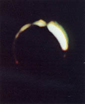
“Exceptional first photograph of an eclipse of Sun by the Earth, as seen from the surface of the Moon, Surveyor III, 24 April 1967”

Above per the description associated with a black & white version of another Surveyor III photo of this particular solar eclipse, as written by Victor Martin-Malburet…from a 2022 auction of his photographs conducted by Rago Wright, LLC. At:

search.app/oY8ManvGnKh3UmdB8

Further:

“Both sunrise and sunset on Earth are seen in this photo of the Earth’s disc passing across the sun as photographed from a vantage point on the moon. The picture was taken by Surveyor III’s television camera at 3:24 a.m. PST during the April 24 eclipse. On the upper left side of the disc, the sun is setting over Asia and the Indian Ocean. Lower right edge shows sunrise over the southeast Pacific. At this stage of the eclipse, the Earth and sun are 42 minutes into the period to totality. Brightest portion of the lighted ring around the Earth is in the northwest quadrant of the Earth as viewed from the moon. This is the eastern portion of the Asian Continent.”

Above, along with the photo, at/from the superlative LPI website:

www.lpi.usra.edu/resources/mapcatalog/Surveyor/press_rele...

Specifically:

www.lpi.usra.edu/resources/mapcatalog/Surveyor/press_rele...

Additionally, per NASA SP-184/“Surveyor Program Results”, from the section entitled "Eclipse of Sun by Earth, as Seen From Surveyor Ill", authored by "E. M. SHOEMAKER, J. J. RENNILSON, AND E. A. WHITAKER:

“In late morning of the first lunar day of the Surveyor III mission, an unusual opportunity occurred to observe an eclipse of the Sun by the Earth; this eclipse took place on April 24, 1967. Were it not for the fact that the spacecraft was tilted as much as 14.7° to the west and was oriented favorably with respect to azimuth, it would not have been possible to observe the Earth from a landing site at 23° W longitude because of the limited range of elevation angles through which the mirror can be stepped. To observe the Earth, the mirror was pointed upward and positioned at its highest permissible elevation step, and wide-angle pictures of the eclipse were obtained. The image of the Earth was reflected from very near the upper edge of the mirror. During the eclipse, two series of pictures (20 pictures total) were obtained through the color filters. The first series of pictures was obtained at approximately 11:24 GMT; the second set was obtained approximately 37 minutes later: The pictures were taken at two iris positions, and multiple pictures were taken through each filter.

During the eclipse, the Sun passed behind the Earth along a path that brought the position of the center of the Sun, as seen from the Moon, to within 15 minutes of the sublunar point on the Earth. At the time the Sun was most nearly centered behind the Earth, the projected center of the Sun lay northeast of the sublunar point. The sublunar point was at about 172° W longitude and 12.5° S latitude at the time the first series of pictures was taken, and at about 179° E longitude and 12.5° S latitude at the time the second series of pictures was taken. These positions are in the southwest Pacific. The limb of the Earth lay along western North America, the eastern Pacific, eastern Antarctica, the central Indian Ocean, southeast Asia, central China, eastern Siberia, and a short arc across the western Arctic Ocean.

In the first series of eclipse pictures, the Earth is partly surrounded by a halo of refracted light that varies greatly in brightness from one position to another along the limb. A very bright region, approximately 60° in arc length, lies along the northern part of the limb, nearest the position of the Sun. In the majority of pictures taken, parts of the image of the halo in this region are saturated. On either side of this bright region, the halo has a beaded appearance; small bright areas of short arc length are separated from other bright areas by sectors of the halo that are relatively faint. Most of these bright areas or beads are only a few degrees in length, but one relatively bright sector, about 20° long, is present that cannot be resolved into separate beards. At least 12 beads can be distinguished in the halo.

A gap ranging from about 50° to more than 90° is present in the images of the halo along the eastern limb of the Earth. Over most of the arc length of the gap, the halo is too faint to be detected with the exposures used, but over a short sector of the gap, the image of the Earth may have been cut off by the edge of the camera mirror.”

Note the lead author, none other than the man himself, Eugene M. Shoemaker.

The above at/from:

search.app/ibJEAHwSUcftLPyo9

and/or:

search.app/VrgotrvWU2m5KhaK9

Finally…interesting:

cohost.org/rc/tagged/eclipse?refTimestamp=1707980265964&a...
Credit: Brandt Hughes/cohost

And:

earthsky.org/upl/2015/04/sun-eclipse-by-Earth-from-moon-S...
Credit: EarthSky website

A genuinely rare photograph, for multiple reasons, in color at that!

surprog_v_bw_o_n (ca. 1961-64, Boeing photo no. 2A279739) by Mike Acs

© Mike Acs, all rights reserved.

surprog_v_bw_o_n (ca. 1961-64, Boeing photo no. 2A279739)

An engineering, structural, thermal…or something like that model/mock-up of a Surveyor lunar lander is lowered into/raised from? the black maw of a 50-foot-high space environment chamber at the Boeing Space Center near Seattle, Washington. Circa 1961-64?
Is the big round thing an early representation of a high gain antenna?

Although probably not uncommon, I nonetheless found it interesting that a Hughes Aircraft Company product was in a Boeing Company facility. I suppose if you’re the only one with a vacuum chamber & the other party has the money, it’s all good. In fact, in researching this symbiotic arrangement, Boeing currently touts its availability of just such a capability:

www.boeing.com/company/key-orgs/boeing-testing-services/e...
Credit: Boeing website

1/8 Scale Surveyor Model (NASA HQ, control no. 5264, overhead view) by Mike Acs

© Mike Acs, all rights reserved.

1/8 Scale Surveyor Model (NASA HQ, control no. 5264, overhead view)

Exceedingly rare 1/8 scale NASA-manufactured model of the Surveyor lunar lander - precursor to Apollo.

Not unlike Surveyor III, a previous USPS-induced "landing" may have involved a bounce or three. I believe (not all seen here) that I have all of the pieces.
Fortunately, in a minor miracle, I came upon a second-generation copy of the plans/blueprints for this model (from someone else) some time after acquiring the model. Hopefully it’ll be of assistance in the highly anticipated restoration. Not by me of course.

surprog_v_bw_o_AKP (ca. 1967, poss. Hughes Aircraft Co. photo, no. 8S00775) by Mike Acs

© Mike Acs, all rights reserved.

surprog_v_bw_o_AKP (ca. 1967, poss. Hughes Aircraft Co. photo, no. 8S00775)

A bold & striking Hughes Aircraft Company (I believe) artist’s concept depicting a nominal Surveyor mission profile. Prepared prior to/in anticipation of the final Surveyor mission, previous successful Surveyor landing sites are marked by Surveyor spacecraft figures across the face of the moon. That final mission, Surveyor 7, is prominently depicted as zeroing in on its destination in vicinity of Tycho Crater.

One of the few/uncommon black & white prints on “A KODAK PAPER” photographic paper from this period confirms this to have been meant for prime-time usage/presentation/press release(s). Despite obvious handling & mild yellowing, the image is exceptionally crisp & literally, lustrous.

Unfortunately, there’s no signature present.

See slide no. 17:

slideplayer.com/slide/5136051/
Credit: “SlidePlayer” website

vil2_v_c_o_TPMBK (unnumbered, poss. companion to Viking 2-29, P-18665) by Mike Acs

© Mike Acs, all rights reserved.

vil2_v_c_o_TPMBK (unnumbered, poss. companion to Viking 2-29, P-18665)

“Viking Lander 2 took this color picture of the sky at the Utopia landing site Jan. 16, 1977. The view is possibly toward the south/southeast. The picture was taken about noon local lander time. The Sun is just outside the picture to the left, and its brightness has saturated the camera’s sensors. Opacity of the atmosphere has increased with the onset of autumn in northern hemisphere of Mars. Less light now penetrates the atmosphere than during the primary mission period last summer. There are two primary causes: an ice fog develops during the night and lasts through the morning. Soil particles suspended in the atmosphere have also increased. Extremely fine soil particles suspended in the atmosphere preferentially absorb blue light, producing the reddish color of the Martian sky.”

The above is per the caption I found for what I think to be a companion/associated image, with my editorial 'revision' based on what’s in the photograph.

Confirmation of it at least being Utopia Planitia:

www.msss.com/mars/pictures/viking_lander/l2c1pmq2q3.jpg
Credit: Malin Space Science Systems website

surprog_v_c_v_litho (ca. 1966-68, Ryan Aeronautical promo portfolio, plate no. 5) by Mike Acs

© Mike Acs, all rights reserved.

surprog_v_c_v_litho (ca. 1966-68, Ryan Aeronautical promo portfolio, plate no. 5)

surprog_v_c_o_litho (ca. 1966-68, Ryan Aeronautical promo portfolio, plate no. 5) by Mike Acs

© Mike Acs, all rights reserved.

surprog_v_c_o_litho (ca. 1966-68, Ryan Aeronautical promo portfolio, plate no. 5)

“All of the instrumented Surveyor spacecraft which have landed on the Moon have been controlled in the final minutes before touch-down by Ryan landing radars. Ryan’s Doppler radar equipment provides the necessary velocity and altitude data to accomplish the “soft” landing.”

~8.5” x 11”. Printed on a lightweight, satin-like, lightly textured ‘presentation’ paper.

Plate number 5 of a Ryan Aeronautical / CMC (Continental Motors Corporation), Wisconsin Motor Corporation presentation portfolio. A really unique and dynamic pen/watercolor (I think) work by Robert C. Kinyon.
An unexpected “WIN” due to finding him at “THE UNITED STATES AIR FORCE COLLECTION”. At:

www.afapo.hq.af.mil/Public/Presentation/Artists/artistsde...

I’ve actually pulled a few other folks from here. Kudos!

Viking Lander on Mars, by Jim Butcher (internet download) by Mike Acs

© Mike Acs, all rights reserved.

Viking Lander on Mars, by Jim Butcher (internet download)

A very nice depiction of a Viking Lander on the Martian surface, by artist James “Jim” Butcher.

I’m ALL ABOUT giving credit/attribution where credit & attribution is due. Not to mention, it’s the right/only thing to do. I wish others abided by this as well…although, not so much. Surprise.
However, NOT in this case, for good - albeit petty - reason. Although the resolution is not optimal, at least it’s ‘out there’ now. A “WIN” of a different flavor! 👍

Outstanding. And he’s still a ‘kid’!:

portraitcollection.jhmi.edu/artists/james-butcher
Credit: “The Johns Hopkins Medical Institutions” website

A nice sampling of Mr. Butcher’s works, sprinkled with a few others on behalf of NASA.

www.invaluable.com/artist/butcher-jim-q52zydzf0v/sold-at-...
Credit: Invaluable website

LO III_v_bw_o_n (ca. 1966-67, unnumbered press & poss. NASA photo) by Mike Acs

© Mike Acs, all rights reserved.

LO III_v_bw_o_n (ca. 1966-67, unnumbered press & poss. NASA photo)

“SKETCH III:
One of primary targets for Lunar Orbiter photo craft will be site where Surveyor I soft-landed on the moon to return more than 11,000 pictures from the lunar surface. Surveyor’s flat-faced solar panel and high-gain antenna have been positioned to the largest possible shadow to aid in catching Lunar Orbiter’s photographic eye. Photographs taken by Lunar Orbiter as low as 28 miles will permit precise study of terrain surrounding Surveyor site, as well as eight other proposed manned landing sites lying along lunar equator.
LOS ANGELES TIMES SYNDICATE”

Gorgeous. Russ Arasmith.

The same image:

www.nasa.gov/centers/marshall/history/russ-arasmith-apoll...

Two others:

www.nasa.gov/centers/marshall/history/russ-arasmith-lunar...

www.nasa.gov/centers/marshall/history/russ-arasmith-lunar...

vil_v_bw_o_n (ca. 1970, Martin Marietta Corp. photo, poss. no. DP 7629) by Mike Acs

© Mike Acs, all rights reserved.

vil_v_bw_o_n (ca. 1970, Martin Marietta Corp. photo, poss. no. DP 7629)

“CONCEPT OF VIKING LANDER TO BE LAUNCHED TO MARS IN 1975

Robot Spacecraft to Search for Life in the Martian Soil.”

Also:

“The Viking lander design went through a number of versions in 1968 and 1969. The three-legged September 1969 design added a second camera for stereophotography and moved the meteorology instrument to the high-gain antenna mast.”

At:

history.nasa.gov/SP-4212/p218b.html

Disregard the terminal propulsion nozzles (3 places) being also labeled as “fuel tanks”…ugh. Proofreading anyone?

Possibly on display…at Martin Marietta’s Denver HQ?

A subsequent design iteration…also in the same…building…lobby?

www.gettyimages.com/detail/news-photo/the-viking-lander-w...

sur01_v_bw_o_n (66-H-824, pseudo Surveyor 1-20 eq) by Mike Acs

© Mike Acs, all rights reserved.

sur01_v_bw_o_n (66-H-824, pseudo Surveyor 1-20 eq)

“Photograph from National Aeronautics and Space Administration’s Surveyor I spacecraft. Spherical mosaic of narrow-angle photographs of the Lunar scene at low sun illumination. Craters and fine detail of the surface enhanced by the low oblique lighting. Center of mosaic is southwest of spacecraft. Tilt of horizon is due to non-verticle mounting of the camera. The picture was received at the National Aeronautics and Space Administration’s Jet Propulsion Laboratory.”
Yes, “verticle”…I’ll leave it alone.

It’s a cool image & historic, but I don’t like it being cropped at the horizon. Actually, I don’t like any of the cropping they did. Why?

The mosaic (for all intents & purposes), labeled as ‘Surveyor 1-20’ by the Lunar and Planetary Institute (LPI), were taken/assembled in order to provide an identical view to ‘Surveyor 1-19’, but at a different illumination angle. It/they were also then combined with ‘Surveyor 1-21’ in order to provide a complete 360-degree view of the landing site.

All per/at the wonderful LPI website:

www.lpi.usra.edu/resources/mapcatalog/Surveyor/press_rele...

Specifically:

“Surveyor 1-19

Spherical mosaic of narrow-angle photographs of the lunar scene taken by Surveyor I on June 12, 1966, two days before nightfall on the moon. Each photo chip is two inches square and represents a six-degree field of view as seen by Surveyor’s TV camera. The pictures are arranged on the concave surface of a three-foot hemisphere to form the panorama. The sun is shining from the west (right). Tilt of the horizon is due to off-vertical mounting of the camera on the spaceframe. The scene portrayed is the same as that shown 24 hours later with the sun at a lower angle in picture #20.”

Image at:

www.lpi.usra.edu/resources/mapcatalog/Surveyor/press_rele...

“Surveyor 1-20

Mosaic of narrow-angle pictures of moon taken by Surveyor I’s television camera forms a panoramic view of lunar terrain stretching approximately 130 degrees across horizon. Each photo chip is two inches square and represents a six-degree field of view as seen by the camera. The pictures are mounted in overlapping fashion against the concave surface of a three-foot hemisphere. When completed, the hemispheres in pictures #20 and #21 will form a complete 360-degree view from Surveyor. The narrow-angle survey was made June 13, about 24 hours before sundown on the site pictures.”

Image at:

www.lpi.usra.edu/resources/mapcatalog/Surveyor/press_rele...

“Surveyor 1-21

Mosaic of narrow-angle pictures of moon taken by Surveyor I’s television camera forms a panoramic view of lunar terrain stretching approximately 115 degrees across the horizon. Dramatic elongated shadow of the spacecraft was created by the low sun sinking on the horizon behind Surveyor. Each photo chip is two inches square and represents a six-degree field of view as seen by the camera. The pictures are mounted on the concave surface of a three-foot hemisphere. When completed, the hemispheres in pictures #21 and #20 will form a complete 360-degree view from Surveyor. Parts of the spacecraft identifiable at left are (from top) one of the antenna booms, helium tank, nitrogen tank (cantilevered on braces) the auxiliary battery. The survey was made June 13, about 24 hours before sundown on the site pictured.”

Image at:

www.lpi.usra.edu/resources/mapcatalog/Surveyor/press_rele...


Also:

www.smithsonianmag.com/air-space-magazine/surveyor-1-amer...
Credit: Smithsonian Magazine online website

Last, but NOT least:

“EUGENE M. SHOEMAKER, Chief, Astrogeology Branch, U.S. Geological Survey, commented on the scene:

"It shows the intricately cratered surface of the Oceanus Procellarum. It is a gently undulating surface pockmarked with craters, ranging from a few centimeters to several hundred meters in diameter, and littered with blocks and fragments, ranging from less than a millimeter to more than a meter across. The craters and the fragmental debris were probably formed by bombardment of the lunar surface by meteoroids and by pieces of the Moon itself, hurled through space from larger craters.

"The pitted appearance of the lunar surface [which one observer has likened to that of a World War I battlefield] is enhanced by the presence of long shadows, extending away from the spacecraft's foot and the more prominent blocks, due to the low angle of incidence of the rays of the evening Sun."

Above at/from:

history.nasa.gov/SP-168/section2a.htm

a12_v_bw_o_n (69-H-1772, (AS12-48-7119)) by Mike Acs

© Mike Acs, all rights reserved.

a12_v_bw_o_n (69-H-1772, (AS12-48-7119))

“A close-up view of the unmanned Surveyor III spacecraft footpad, photographed during the second extravehicular activity period (EVA-2) of Astronauts Charles Conrad, Jr., Apollo 12 mission commander, and Alan L. Bean, lunar module pilot. Their Apollo 12 lunar module landed Nov. 19, 1969m, in the Ocean of Storms some 600 feet away from the Surveyor III spacecraft. The Surveyor III landing took place in the Ocean of Storms on April 19, 1967. Apollo 12 was the second manned lunar landing mission.”

Transcript leading up to & during the photograph taken:

“134:10:47 Conrad: I think you ought to photo that scoop (means "footpad") there, the way it dug in.
134:10:50 Bean: I did.

134:10:52 Conrad: There's no way that thing can slide down the hill on us, the way it's dug in.

134:10:57 Bean: Uh-uh. Okay, now let me get that footpad. That's a beautiful shot there. We're going to do footpad 3, I guess it is, or is that 1?

134:11:05 Conrad: Footpad 3.

134:11:06 Bean: Okay. And that's going to be in f/8, probably. It's pretty low; let me try 5.6. (To Houston, louder than he's been talking to Pete or, for that matter, to Houston, lately) That aft honeycomb shock absorber struck the dirt and looks like it took some of the shock. Other than that, the front one didn't appear to do that. Stereo there. Sure isn't going to slide down the hill though, that's for sure.

[Al's photos of footpad 1 (downslope) are AS12-48- 7119 and 7120.]”

Above & photograph at:

www.hq.nasa.gov/alsj/a12/a12.surveyor.html

Specifically:

www.hq.nasa.gov/alsj/a12/AS12-48-7119HR.jpg
Both above credit: ALSJ website

vilo1/2_v_bw_o_n (76-H-314) by Mike Acs

© Mike Acs, all rights reserved.

vilo1/2_v_bw_o_n (76-H-314)

“This is an artist’s conception of the sequence of events that will take place just prior to landing a life-detection laboratory on the surface of Mars on July 4, 1976. Above right, the Viking spacecraft, composed of an orbiter and a lander, has been in orbit around the Red Planet since June 19, 1976, taking pictures of the planned landing site to ascertain its safety before releasing the lander (top, left) for its three-to-five-hour descent. Protected by aeroshells, the heat-sterilized lander hurtles into the thin Martian atmosphere at a speed of about 10,000 mph, to be slowed first by aerodynamic drag until the shell is discarded, then by parachute (center) and finally by retrorockets to assure a gentle landing. Instruments will study the structure and composition of the Martian atmosphere as the lander drifts down. Viking 2 is scheduled to arrive at Mars on August 7 and touch down on the surface on Sept. 4”

Interesting, with minor variations that I assume to be of a latter version(?), labeled as “Viking entry system”:

history.nasa.gov/SP-480/p204.htm

I assume latter only because I can discern/identify what I think is one of the terminal descent engines in the online version. Granted, its omission in my posted photo may just be an oversight.

vil2_v_bw_o_TPMBK (Viking 2-22, P-18066 (Sol 21), PIA00145 eq) by Mike Acs

© Mike Acs, all rights reserved.

vil2_v_bw_o_TPMBK (Viking 2-22, P-18066 (Sol 21), PIA00145 eq)

“Operation of the surface sampler in obtaining Martian soil for Viking 2's molecular analysis experiment last Saturday (September 25) was closely monitored by one of the Lander cameras because of the precision required in trenching the small area--8 by 9 inches--surrounded by rocks. Dubbed “Bonneville Salt Flats,” the exposure of thin crust appeared unique in contrast with surrounding materials and became a prime target for organic analysis in spite of potential hazards. Large rock in foreground is 8 inches high. At left, the sampler scoop has touched the surface, missing the rock at upper left by a comfortable 6 inches, and the backhoe has penetrated the surface about one-half inch. The scoop was then pulled back to sample the desired point and (second photo) the backhoe furrowed the surface pulling a piece of thin crust toward the spacecraft. The initial touchdown and retraction sequence was used to avoid a collision between a rock in the shadow of the arm and a plate joining the arm and scoop. The rock was cleared by 2 to 3 inches. The third picture was taken 8 minutes after the scoop touched the surface and shows that the collector head has acquired a quantity of soil. With surface sampler withdrawn (right), the foot-long trench is seen between the rocks. The trench is three inches wide and about 1 1/2 to 2 inches deep. The scoop reached to within 3 inches of the rock at far end of trench. Penetration appears to have left a cavernous opening roofed by the crust and only about one inch of undisturbed crust separates the deformed surface and the rock.”

Note the dramatically different appearance...of everything, under the different sun angles.

Above and image also at:

photojournal.jpl.nasa.gov/catalog/PIA00145
Credit: JPL Photojournal

vil2_v_c_o_TPMBK (Viking 2-29, P-18665) by Mike Acs

© Mike Acs, all rights reserved.

vil2_v_c_o_TPMBK (Viking 2-29, P-18665)

“Viking Lander 2 took this color picture of the sky at the Utopia landing site Jan. 16, 1977. The view is toward the southeast. The picture was taken about noon local lander time. The Sun is just outside the picture to the right, and its brightness has saturated the camera’s sensors. Opacity of the atmosphere has increased with the onset of autumn in northern hemisphere of Mars. Less light now penetrates the atmosphere than during the primary mission period last summer. There are two primary causes: an ice fog develops during the night and lasts through the morning. Soil particles suspended in the atmosphere have also increased. Extremely fine soil particles suspended in the atmosphere preferentially absorb blue light, producing the reddish color of the Martian sky.”

The only other place I found the image, ugh:

www.granger.com/results.asp?image=0185645&itemw=4&amp...

surprog_v_bw_o_n (1962 press photo, from orig. Martin Co. photo no. 8P-67736) by Mike Acs

© Mike Acs, all rights reserved.

surprog_v_bw_o_n (1962 press photo, from orig. Martin Co. photo no. 8P-67736)

“BALTIMORE, April 19 [1962] -- MAN ON THE MOON -- This is an artist’s concept of the Surveyor spacecraft, a nuclear-powered automatic laboratory designed by the National Aeronautic[s] and Space Administration. The moon craft is scheduled for launching by the United States and landing on the moon to gather data for later manned landings. Hughes Aircraft Company will build the spacecraft, with the Martin Co. of Baltimore building the atomic power-pack (near center). The power-pack was designed by the Atomic Energy Commission.”

Huh…say what?

Who knew?
Did YOU??
I DIDN’T!!!

As if the above atomic 😉 bombshell (to me) wasn’t enough, the obscure concept is by the hand of yet another Martin Co. ‘mystery’ artist/illustrator…”OLIVARI”.
What a “Dream Team” of superior, yet nearly anonymous, talent: DiPietro/Gorsuch/Fahdt/Olivari!
Nothing on Mr./Ms. Olivari.

Although a little out of context without copy/pasting page upon page upon page, some excellent & informative background:

“Many of the original RTG team thought of the early years after Seaborg (Glenn Seaborg: AEC Chairman) came to the AEC as the “golden days” of the AEC— before the big and costly space systems and missions of NASA involved increasingly large numbers of people and organizations in the RTG program. From 1962 to 1965, the antinuclear movement was not yet vociferous, the future of nuclear power and its widespread uses looked promising, and the chairman of the AEC was a scientist who believed strongly in nuclear power and its wedding to space ventures. Moreover, Seaborg inspired loyalties and a sense of common purpose in the people of the AEC. Carpenter (Robert T. Carpenter: head of the isotope office of the SNAP Program) recalled that it was common to meet the top man in the halls at AEC’S Germantown building and to be greeted by name and asked questions about the program: “We had a personal relationship with Seaborg, and we also had a close arrangement with the Commissioners.” He added that problems on the Hill were few and that the program received support from both the AEC and the Congress, whose members pressed for a flight schedule on space nuclear propulsion, eager to see the SNAP-isotope technology get its chances to fly. In those years, according to Carpenter, the AEC allowed engineers to do everything from start to finish on their programs-at least on the small isotopic power program. The RTG group chose to have just a few hands holding all the reins. Carpenter recalled: “I prepared budget documents, defended them before Congress, ran my program and participated in the launches.”
Carpenter explained that few contractors were involved in the early days because the program was small and there wasn’t a great deal of money available for space-isotopic power development. He indicated that SNAP-3 was built on a purchase order from the Martin Company to the 3M Company for a very small amount Martin got involved in isotopic power, while others held back, because “they were into space in a big way and their programs were long range. A lot of other firms that got involved later came in when there was more money in the budgets. Like when we got going on Apollo.”
In the initial development period, the circle was limited, encompassing the small group at the AEC and small groups in other institutions the isotope power experimenters and developers at Martin-Baltimore and their subcontractors at 3M the fuel packagers at Monsanto’s Mound Laboratory and users
such as the Applied Physics Laboratory of Johns Hopkins University which developed the Transit navigational satellite system for the Navy. This team proceeded to develop the SNAP-9A with its increased power requirements for the operational Transit scheduled for flight in late 1962. At the same time, a series of SNAP-7 devices were under development at Martin for use by the Navy, Coast Guard, and Weather Bureau for navigation lights and weather stations on earth.
NASA began to enter into contracts with the AEC to study possible applications of isotopic SNAPS to future space missions. Even before Apollo, NASA recognized that there would be unusually severe power system requirements for lunar missions “due to the weight and space limitations of payload, the
14-day lunar nights, and the variety of the intended experiments.’” By the fall of 1961, NASA reconfirmed its requirements for an isotopic power unit for the Surveyor soft lunar landing mission and the AEC prepared to provide two SNAP devices—designated SNAP-11s—to NASA for missions scheduled to take place two years later. In mid-1962 NASA began preliminary discussions with the AEC on the possibility that an RTG could provide primary power requirements for one of a series of satellites called Interplanetary Monitoring Probes. Along with foreseen technical advantages, NASA hoped to use the
RTG to enhance its own “capability and experience in the use and application of nuclear devices.”
Reporting to the JCAE in September 1962 on space nuclear power applications, Commissioner Hayworth of the AEC stated “Nuclear power not only will enhance space exploration; its use, both for propulsion and for auxiliary power, is the key to extensive outer space exploration.” He reviewed the developments
and tests in the Rover program to develop nuclear rocket propulsion and admitted that there had been disappointments causing delays. Turning to the isotopic power side of the SNAP program, Hayworth reported with “considerable satisfaction” on program successes launchings in June and November of
the previous year of isotope power devices on Navy Transit navigational satellites. Looking to the future, he said, “We are continuing to work closely with DOD and NASA to satisfy their requirements for space SNAP devices, and... we have developed a plutonium 238 fueled 25-watt unit, SNAP-9-A, for
use in the Navy’s operational prototype Transit satellites.” Hayworth also spoke of the work with NASA on the development of the SNAP-11, a 25-watt curium-242 fueled thermoelectric generator planned for powering the Surveyor soft landing lander.
Thus, NASA readied itself for the time when it would become the major user of the isotope units and the small RTG group would open its membership to growing numbers of people and organizations.”

Above from/at:

fas.org/nuke/space/history.pdf
Credit: Federation of American Scientists website

Also:

“Because of the Centaur design changes, Surveyor also had to shed some mass. The new design called for a somewhat lighter 950-kilogram lander carrying only 52 kilograms of instruments. Advanced design work continued and several new options were added to the lander’s design, including the use of a Martin-Marietta SNAP-11 nuclear generator to supply Surveyor A with 18.6 watts of power for ninety days. While this was only a fraction of what was needed to operate Surveyor, this generator would supply minimal power during the long lunar night when the solar panels would be useless. By the end of 1962, plans called for seven Surveyor A landing missions starting in late 1964 and five Surveyor B orbiters with the first launch expected in 1965. Options for five or more additional landers were also being considered.”

Above from/at:

www.drewexmachina.com/2016/05/30/surveyor-1-americas-firs...
Credit: Andrew LePage/Drew ExMachina website

en.wikipedia.org/wiki/Systems_for_Nuclear_Auxiliary_Power
Credit: Wikipedia

fut-lnr_v_bw_o_n (1958, Martin Co. (Info. Svcs.) photo no. 8P-62876) by Mike Acs

© Mike Acs, all rights reserved.

fut-lnr_v_bw_o_n (1958, Martin Co. (Info. Svcs.) photo no. 8P-62876)

“An unmanned probe fires sampling rockets at the Moon's surface to test its structure and composition. Note the antennae for sending data back to Earth. In the background another probe takes off after having made a soft landing on the Moon's surface. (Martin Information Services)”

Thanks to Leo Boudreau, I assume the above to be a quote/extract from “Rocket to the Moon”, 1958, by Erik Bergaust & Seabrook Hull.

Along with Mr. Boudreau’s excellent synopsis:

“The book presents the best information, ideas and assumptions on the conquest of the moon as of 1958. The authors, who were experts on missiles and space flight, tell how the moon would be approached, first with instrumented probes and then with man himself as a payload. Fascinating conjectures, based on the latest scientific findings, show what life on the moon might be like, how men would build a base there, how they would explore the moon, and how they would push on from there to further explorations of outer space.”

All of the above is at Mr. Boudreau’s linked image below!

Lastly, the artist is the truly enigmatic Nick Stanilla…there’s literally NOTHING of/on his life. What little I came across was indirectly in searching on “Stoiko – Cross”, which seems to have been a publishing(?)/writing(?) collaborative comprised of Michael Stoiko and a Mr. Cross. There’s also nil on Mr. Cross and/or the collaboration.
Again, at least Mr. Stanilla came up (indirectly), as having provided his talent to a 1959 Stoiko-written work, co-authored with Donald Cox, entitled “Man . . . in the Universe”.
What appears to be a delightful review of the book, in the “Journal of the Franklin Institute”, 1959, Vol. 268, Issue 2 reads as follows:

“There are many who would like to learn a good bit more concerning the solar system and the universe beyond. In most cases when we look for something like this, it is found wrapped up in such a forbidding array of mathematical symbolism and abstruse figures that discouragement is instantaneous. There should be other books—primers—which forego the formalism of the textbook and try only to be descriptive. Only occasionally will such a book appear. “Man . . . in the Universe” is an excellent example of such a primer.
This is one of the most attractive little books dealing with the solar system with a space travel flavor. The authors are prominent men in their field who have combined skills to produce a most readable and informative book. Each page of text is accompanied by a brilliant picture superbly rendered by an accepted master of the space age art, Nick Stanilla. The combination of text and art is precisely the right mixture for the busy life we lead today. For a true capsule treatment of the solar system and other celestial objects, this book is recommended.”

Above at/from:

af.booksc.eu/book/2112642/a60e3f
Credit: Z-library website

Another excellent collaborative of the three is “SPACEPOWER: What It Means To You”, also from 1958, in which Mr. Stanilla’s wonderfully rich “retro-futuristic” style is fully on display.
A bittersweet partial “WIN” I suppose.

a12_v_bw_o_n (AS12-48-7093) by Mike Acs

© Mike Acs, all rights reserved.

a12_v_bw_o_n (AS12-48-7093)

“This is Surveyor III as seen by Apollo 12 astronauts launched from the Kennedy Space Center on November 14, 1969. Surveyor III, launched from Cape Kennedy on April 17, 1967 made a soft landing on the Moon’s Ocean of Storms on April 19, 1967. Details of the crater’s western wall are obscured by the brilliant rays of the rising sun. Portions of the Surveyor were removed by Astronauts Charles Conrad and Alan Bean and returned to Earth for study.”

In this photograph, taken by Alan Bean, Surveyor III's no. 2 footpad, upon which the the soil clod was deposited by the sampler arm, is facing toward Bean. In fact, the clod can be seen as the darkened area atop the right side of the footpad, along with evidence of the trenches dug by the sampler, also seen as the darkened/shadowed regolith to the right of the footpad.

vil1_v_c_o_TPMBK (verso stamped P-18111BC, poss. 12A240 eq) by Mike Acs

© Mike Acs, all rights reserved.

vil1_v_c_o_TPMBK (verso stamped P-18111BC, poss. 12A240 eq)

“Color-enhanced image of sunset on Mars, recorded by the Viking 1 lander. Part of the spacecraft is just visible at bottom right, colored dark blue. The contouring effect around the setting sun is a result of the imaging system.”

Disappointingly, the image and the above, which may have been part of the original NASA caption, seem to only be available at the ‘pay to play’ sites.

A high contrast version is contained within:

history.nasa.gov/EP-177/ch8-2.html

Although I can see how this has an artistic, mod/pop…whatever it’s called, appeal, I’ve always disliked it. Yet it seemed to have been oft-reproduced. I remember seeing it as a poster, lithograph of course…I think even in NASA/JPL informational/promotional material.
It definitely looks way better as an actual photograph print, not the garish, ‘HDR’, end of “2001: A Space Odyssey”, comic book-like look I seem to recall & refer to above.

i.discogs.com/kAPI00d2TdTseTZwVL5YXOR03oD9osbsjRzeG_z1zbk...

i.discogs.com/Lc1xLVGuQIhLAr66dCTnXmd-qAXxrQPVuiUYqO3HBOU...
Credit: Both above credit Discogs website

Further, although the image is subdued & accurate, the ‘contour lines’ do seem to match. Maybe just processed differently? IDK:

“Viking 1 Lander image of a Martian sunset over Chryse Planitia. In this image the sun is 2 degrees below the local horizon. The banding in the sky is an artifact produced by the incremental brightness levels of the camera. This image was taken on the 30th Martian day (sol) after touchdown, at 19:13 local time. The camera is pointing towards the southwest.”

At:

nssdc.gsfc.nasa.gov/imgcat/html/object_page/vl1_12a240.html
Credit: NSSDCA website

Also:

commons.wikimedia.org/wiki/File:Viking_sunset.jpg
Credit: Wikimedia Commons

Finally, featured on the cover. The right half of it that is:

ntrs.nasa.gov/citations/19800009678