The Flickr Mercuryspacecraft Image Generatr

About

This page simply reformats the Flickr public Atom feed for purposes of finding inspiration through random exploration. These images are not being copied or stored in any way by this website, nor are any links to them or any metadata about them. All images are © their owners unless otherwise specified.

This site is a busybee project and is supported by the generosity of viewers like you.

BJ(1) launch_front (original painting, ca. 1959-65) by Mike Acs

© Mike Acs, all rights reserved.

BJ(1) launch_front (original painting, ca. 1959-65)

A striking original artwork – unfortunately, by an anonymous/unknown artist - of the September 9, 1959, launch of Big Joe/BigJoe 1, the first spacecraft launched as part of Project Mercury.

20” x 30”. I have no idea of the medium used. The finish is very flat (non-lustrous) and of absolutely minimal relief. Despite the purported capability of my iPhone 15 Pro Max, it failed to accurately pick up/capture some of the shades/nuances of color used by the artist, despite my using natural lighting as illumination.
For whatever it’s worth, as an honorable individual, I ALWAYS err, if anything, on the side of 'lessening' the appearance of everything I post on Flickr. Bottom line: This photo really doesn’t do the piece justice.

As if appearance wasn’t enough, its provenance, albeit obscure, is also notable, to me at least:

“Dr. Ernest N. Petrick, son of the late Rev. Fr. Aurelius and Anna Petrick, died Saturday, May 30, 2015, at home, surrounded by his family. Ernest was married to Magdalene Simcoe, father to Deborah (Healey), Katherine, Denise, Victoria (Kropp), grandfather to Michael (Katie Steele), Alexander, and great-grandfather to Ferris (Healey).

Ernest served with the United States Navy as Lieutenant Commander and spent his naval time during WWII as the Chief Engineer aboard the USS William D Porter DD 579. He received his BS in Mechanical Engineering from Carnegie Institute of Technology, his MS and his PhD from Purdue University. He worked on a variety of research projects throughout his lifetime spanning from basic combustion to aeronautical engineering in the field of high-temperature air-cooled gas turbine engines. He was Technical Director and Chief Scientist of the US Army Tank-Automotive Command (TACCOM), for the research, development, engineering and testing of the components for automotive, combat and tactical vehicles.

He was an adjunct professor of engineering at the University of Michigan and Wayne State. He received the Outstanding Mechanical Engineering Award from Purdue University and was named Distinguished Engineering Alumnus, Purdue University. He served as a U.S. delegate to NATO.

Ernest was a brilliant, honest, and gracious man whose presence of warmth and quick wit left a treasured gift to everyone whose life he touched. He will be greatly missed.”

Above at/from:

www.dignitymemorial.com/obituaries/ann-arbor-mi/ernest-pe...
Credit: Dignity Memorial website

My date range is based (of course) on the launch date, and per the hand annotation on the back, its presentation to Dr. Petrick (by Don Reid) during 1965. Further, based on his birth year of 1922, the date of 1973 on the affixed DA Form 1818 likely reflects his retirement/departure from his position at U.S. Army Tank-Automotive Command (TACOM), and this being officially passed to his custody at the time.

Continue to Rest In Peace Good Sir. Thank you for your service.

Finally:

en.wikipedia.org/wiki/Big_Joe_1
Credit: Wikipedia

merprog_v_bw_o_n (ca. 1959, unnumbered poss. press photo) by Mike Acs

© Mike Acs, all rights reserved.

merprog_v_bw_o_n (ca. 1959, unnumbered poss. press photo)

In this ca. 1959 artist’s concept, a Mercury capsule is about to reenter earth’s atmosphere. My year estimation is based on its similarity to the below linked image, along with the capsule lacking its shingles and the overall appearance of the retrograde package, i.e. this being an earlier depiction. Note also the “vector shading”(?), indicating that initial atmospheric interaction has commenced, and that the retrograde package is still attached. Other than during MA-6, I don’t know if this would’ve been the case.

Yet another gem by John Gorsuch.

Multiple handling imperfections, only visible when viewed obliquely, do not detract. Still of high gloss, to include a satin-like finish of the verso.

The plight of Friendship 7. by pcarsola

© pcarsola, all rights reserved.

The plight of Friendship 7.

Found Slide by Thomas Hawk

Available under a Creative Commons by-nc license

Found Slide

date stamped on slide August 1965

merprog_v_bw_o_n (ca. 1959, Garrett Corp. photo no. 36032-3) by Mike Acs

© Mike Acs, all rights reserved.

merprog_v_bw_o_n (ca. 1959, Garrett Corp. photo no. 36032-3)

A wonderful, rather quaint Garrett Corporation, AirResearch Division artist’s airbrush depiction of the Mercury Program capsule’s closed-type Environmental Control System (ECS), provided/manufactured by the company. Note the interesting upper torso/upper thigh mesh restraint system.

No artist’s signature is visible.

ma09_v_bw_o_n (63-MA9-54) by Mike Acs

© Mike Acs, all rights reserved.

ma09_v_bw_o_n (63-MA9-54)

“The orbital path achieved for the spacecraft by the Atlas will be the result of split-second programming of launch vehicle staging, velocity, pitch-over, yaw control and engine cutoff. The Atlas will accelerate continuously during its powered flight and must arrive at the insertion point traveling at a precise speed, completing its pitch-over to an Earth-referenced horizontal flight path at the same moment it reaches that orbital point.”

The image was featured on the cover of a NASA publication titled ““MA-9 TRACKING AND COMMUNICATIONS NETWORKS”.

ma06_v_bw_o_n (ca. 1961, unnumbered, poss. Convair/General Dynamics photo no. 67532 A eq) by Mike Acs

© Mike Acs, all rights reserved.

ma06_v_bw_o_n (ca. 1961, unnumbered, poss. Convair/General Dynamics photo no. 67532 A eq)

Artist’s depiction of Mercury capsule (no. 13) separation from its Atlas LV-3B/Atlas-D booster (serial no. 109D) during John Glenn’s historic MA-6 earth-orbital mission. Gorgeous artwork by Convair/General Dynamics artist John M. Sentovic. A wonderful & appropriate combination of the “Right Stuff” in artist and of course, the original “Right Stuff” in Astronauts.

Thank You Gentlemen – Continue to Rest In Peace.

The image was featured in “ONE… TWO… THREE… AND THE MOON!”, NASA EP-7 (Revised 6-63), with the following caption:

“Artist’s conception of Mercury spacecraft separating from Atlas in orbit.”

A Must Read:

e05.code.blog/2022/04/19/meet-john-sentovic/
Credit: Garrett O’Donoghue/’numbers station’ blog

A Must Watch/Listen:

www.youtube.com/watch?v=5n449Q_xeUs
Credit: Andrew Chaikin/collectSPACE/YouTube

Although apparently having been glued to a lightweight black construction paper (prevalent from the time period), it was likely within a binder, folder or something similarly protective, as it’s in very nice condition.

mr03_v_c_o_AKP (USAF photo no. 61C-957, S-61-01927 eq) by Mike Acs

© Mike Acs, all rights reserved.

mr03_v_c_o_AKP (USAF photo no. 61C-957, S-61-01927 eq)

“Corps of Engrs.
Redstone with capsule.”

Wow…not counting the “Corps of Engrs.” line, that’s only three words. I don’t think a caption can get any shorter. Unless, maybe something like “Blast off.” or “Big rocket.”

Per the NASA issuance of the photograph. I’m sure there are a few other ‘official’ versions:

“Mercury-Redstone 3 (MR-3), the United States' first manned spaceflight, is launched from Cape Canaveral on a suborbital mission. Astronaut Alan B. Shepard Jr. was the pilot of the Mercury spacecraft, designated "Freedom 7". The spacecraft attained a maximum speed of 5,180 miles per hour (mph), reached an altitude of 116 1/2 statute miles, and landed 302 statute miles downrange from Cape Canaveral, Florida.”

mga_v_bw_o_n (LOC 63C-3233, 11-5-63; M-MS-G-77-63, SEPT 6, (prob 1963)) by Mike Acs

© Mike Acs, all rights reserved.

mga_v_bw_o_n (LOC 63C-3233, 11-5-63; M-MS-G-77-63, SEPT 6, (prob 1963))

“CHART: Capsule Comparison. Shot for Heiser & Deberk.”

A wonderful & most gratifying find…in several ways. First, I’d never seen this particular ‘capsule comparison’ depiction; ranging from the Mercury capsule’s non-standard cutaway depiction, i.e., it pointing away, to the Apollo Command Module being of the Direct Ascent variety, with periscopes extended (although pointing in the wrong direction).
Most significantly – in my world – the Gemini capsule depiction – the only spacecraft firing its reaction control system thruster btw – in combination with the sun-earth?/moon? conjunction permitted identification of the artist. That being the (I’m sure unintentionally) enigmatic Arnold Pierce. A major WIN.
This then leads to/supports other similar & derivative early works to also be potentially attributable to Mr. Pierce. Although, I exclusively associated Mr. Pierce to be a McDonnell Aircraft Corporation artist, this however being a Marshall Space Flight Center (MSFC)-issued photo.
Yessiree, too many tedious & pointless observations, but to me, good stuff…preserved.

Heiser: Joseph M. Heiser Jr.?

Deberk: I think this is a botch job of Gerd De Beek, whose position & other "shot for" reference pretty much confirms. If you wish to go down the rabbit hole with me a little, see the below linked TM-1 LEM photo.

merprog_v_bw_o_n (original 1959 press photo, Willment) by Mike Acs

© Mike Acs, all rights reserved.

merprog_v_bw_o_n (original 1959 press photo, Willment)

“ARTIST’S CONCEPTION OF MAN-CARRYING SATELLITE—The National Aeronautics and Space Administration released this artist’s conception of a Project Mercury man-carrying capsule, March 26, in Washington. The NASA said the portion of the earth shown is what an astronaut pilot would see from an altitude of about 120 miles at a point over Cuba.”
Interesting that Cuba was used a ‘reference point’, with the Bay of Pigs (visible in the work), merely two years in the future, along with near-Armageddon in 1962.

Thanks to issuu and it’s posting of “A Century At Langley”, by Joseph R. Chambers, the capsule depiction is seen to be based entirely upon the test article used in the 20-ft Spin Tunnel there. Seen here:

issuu.com/nasalangley/docs/chap1-12_spds/52

An unexpected WIN…especially for a work, particularly of NASA origin, from this early on to retain the artist’s name.
However, if said artist goes by first name-MIDDLE NAME-last name, then damn straight newbie NASA, you’re gonna retain & include all of it. No offense directed at those that subscribe to such, for whatever reason. However, I can’t help but have ‘Charles Emerson Winchester III’ come to mind. Actually, let’s go with David Ogden Stiers. 😉

Also by Mr. Afton Willment/Mr. Wilment. Excellent:

ia600200.us.archive.org/29/items/NIX_EL-2002-00390/EL-200...
Credit: Internet Archive website - also a wonderful unheralded source of amazing imagery, content...you name it.

Too soon, with barely a footprint. Rest In Peace David:

peoplelegacy.com/david_afton_willment-0C405Z
Credit: People Legacy website

SPACE STATION CONCEPTS_(2002, Gary H. Kitmacher-JSC, internet download) by Mike Acs

© Mike Acs, all rights reserved.

SPACE STATION CONCEPTS_(2002, Gary H. Kitmacher-JSC, internet download)

It’s no wonder I’m confused.

A wonderful compilation by Mr. Gary H. Kitmacher/Johnson Space Center, 2002.

At:

www.spacearchitect.org/pubs/IAC-02-IAA.8.2.04.pdf
Credit: AIAA Space Architecture Technical Committee website

I hope nobody sues me for propagating this wonderful, informative, albeit still confusing, graphic presentation.

64NYWF_v_bw_o_n (64-World's Fair-2, poss. neg. no. 8B-64918) by Mike Acs

© Mike Acs, all rights reserved.

64NYWF_v_bw_o_n (64-World's Fair-2, poss. neg. no. 8B-64918)

“U. S. SPACE PARK -- Dominating the extensive display of full-scale spacecraft and rockets at the New York World’s Fair will be the Gemini-Titan II, standing 110 feet tall, as it would be on the launch pad at Cape Kennedy. Other full-scale space hardware to be at the Space Park will be, from left, Apollo Command and Service Modules, the Lunar Excursion Module, Gemini-Titan II, Gemini spacecraft and the Aurora 7 Mercury spacecraft which carried Astronaut Scott Carpenter on three Earth orbits.”

Used for press purposes, permanent "highlight" lines remain. Fortunately, they were precisely traced, so they minimally detract.

Sites abound with additional information and photos. For something off the beaten path:

www.collectspace.com/ubb/Forum18/HTML/001194.html
Credit: collectSPACE website

maXX_v_bw_o_n (ca. 1960-63 Convair/Gen. Dynamics photo no. 56714) by Mike Acs

© Mike Acs, all rights reserved.

maXX_v_bw_o_n (ca. 1960-63 Convair/Gen. Dynamics photo no. 56714)

Convair/General Dynamics artist’s concept of a Mercury-Atlas launch vehicle on the pad. Note the svelte waistline of the Atlas adapter section. To my knowledge, every Mercury-Atlas launch vehicle had a parallel-sided adapter section. Maybe not? Kinda? Sorta? Sometimes?
Unfortunately, and likely due to little else being available, one particular diagram of the “Atlas-Mercury” & Atlas ICBM, printed in “MERCURY ATLAS: MA-6”, an official NASA publication btw, has been replicated/propagated by everybody and their brother. In it, the vehicle does indeed have an obvious waistline. Huh?
A few examples:

www.enginehistory.org/Rockets/RPE05/Mercury-Atlas.jpg
Credit: ‘Aircraft Engine Historical Society’ website

i1.wp.com/www.drewexmachina.com/wp-content/uploads/2019/0...
Credit: Andrew LePage/Drew ExMachina website

Even a version in color:

nickd.freehostia.com/OrbiterVault/download/atlas-mr.gif
Credit: ‘Nick’s Space Center’ website

Views of MA-1. I must admit, the adapter does appear to minimally narrow near its aft end:

i0.wp.com/www.drewexmachina.com/wp-content/uploads/2019/0...

i2.wp.com/www.drewexmachina.com/wp-content/uploads/2020/0...
Both above credit: Andrew LePage/Drew ExMachina website

upload.wikimedia.org/wikipedia/commons/5/5b/Big_Joe_Ready...
Credit: Wikipedia

IDK

No artist signature. Used for press release purposes, some highlighted/outlined areas of the photograph remain…permanently. My impressive new handy-dandy remover couldn't budge them.

ma09_v_bw_o_n (63-2500, S-63-5713 eq) by Mike Acs

© Mike Acs, all rights reserved.

ma09_v_bw_o_n (63-2500, S-63-5713 eq)

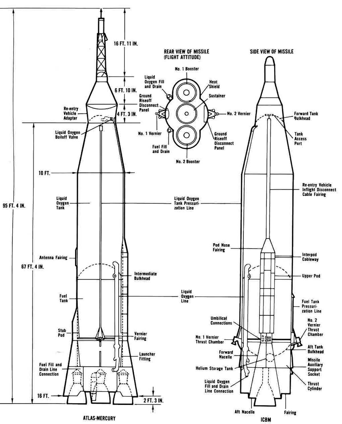
"BALLOON EXPERIMENT -- Drawing shows how the balloon aboard the "Faith 7" spacecraft extends and inflates for aerodynamic studies and visual tests during orbital flight."

Not unlike the artist's depiction of this experiment during the MA-7 mission, the earth is rendered as a cloud covered(?) featureless blob. I wouldn't have signed this either. ;-)

Alas, this experiment was not to be:

“Also on his sixth orbit, after nine hours in space, the astronaut set his cameras, attitude, and switches to deploy a tethered balloon, similar to the one tried on MA-7, for aerodynamic studies of drag and for more visual experiments. The balloon, a 30-inch-diameter Mylar sphere painted fluorescent orange, was to be inflated with nitrogen and attached by a 100-foot nylon line to the spacecraft antenna canister; a strain gauge in the canister should be able to measure the differences in pull on the balloon at apogee (166 miles) and perigee (100miles). Cooper carefully went through his checklist, then tried to eject the balloon package, but nothing happened. He tried again, and still nothing happened. Because the antenna canister was later lost, no one ever knew why the tethered balloon failed to eject. But the second failure of this experiment was more severely disappointing than the first.”

Above per the Astronautix website, at:

www.astronautix.com/m/mercuryma-9.html

“…Another experiment was attempted after 9 hours in flight, during the sixth orbit, when Cooper tried to deploy a balloon but this attempt met with failure. A second deployment effort met with the same results…”

Above per NASA SP-4001, “PROJECT MERCURY: A CHRONOLOGY”, page 192.

Finally:

The following, other than as noted, is from the “MERCURY PROJECT SUMMARY (NASA SP-45)”, at:

history.nasa.gov/SP-45/ch12.htm

“A 30-inch mylar inflatable sphere was packaged in the antenna canister of both the MA-7 (see ref. 1) and MA-9 Mercury spacecraft. These balloons were to be ejected, inflated, and towed at the end of a 100-foot nylon line through one orbital pass to measure the drag experienced by the balloon throughout the orbit. The measured drag could then be readily converted into air density over the Mercury altitude profile. In addition, it was hoped that the astronaut could obtain some sightings yielding visual data on objects in close proximity to the spacecraft.

The design, construction, and qualification of the equipment used on this experiment were carried out by the NASA Langley Research Center. The components of the equipment are shown in figure 12-16. The results of this experiment conducted during the MA-7 flight are contained in reference 1.

[reference 1 being “RESULTS OF THE SECOND U.S. MANNED ORBITAL SPACE FLIGHT, MAY 24, 1962”, specifically:

The objectives of the balloon experiment were to measure the drag and to provide visibility data regarding an object of known size and shape in orbital] space. The balloon was 30 inches in diameter, and was constructed of five equal-sized lunes of selected colors and surface finishes The sphere was constructed of a plastic and aluminum foil sandwich material, and was to be inflated with a small nitrogen bottle immediately after release from the antenna canister at the end of the first orbital pass. In addition, numerous 1/4-inch discs of aluminized plastic were placed in the folds of the balloon and dispersed when the balloon was deployed.. is intended, the pilot observed the rate of dispersion and the associated visual effects of the "confetti."

The balloon was deployed at 01:38:00 ground elapsed time, but it failed to inflate properly. The cause has been attributed to a ruptured seam in the skin. Aerodynamic measurements were taken with the strain-gage pickup, but these are of little use since the actual frontal area of the partial inflated balloon is not known. The visibility portion of the experiment was also only partially successful because only two of the surface colors were visible, the orange and aluminum segments. While the balloon was deployed a series of spacecraft maneuvers evidently fouled the tethering line on the destabilizing flap located on the end of the cylindrical portion of the spacecraft, thus preventing the jettisoning of the balloon. No difficulty was encountered during retrofire and the balloon burned up during reentry.]
The above at:

www.hq.nasa.gov/office/pao/History/SP-6/ch1.htm

Briefly summarized, the balloon was deployed satisfactorily but was only partially inflated; hence, little useful data were obtained on this flight.

By a thorough investigation of the MA-7 failure, it was concluded that the balloon failed to inflate because one of the seams connecting the many gores comprising the balloon skin pulled apart.

The experiment was believed to have been of sufficient value to be repeated on a later Mercury flight; therefore, new equipment was developed and qualified for the MA-9 flight. Careful control of balloon construction was maintained throughout the development program and numerous deployment and inflation tests were conducted by the Langley Research Center to insure the quality of the device. These tests were conducted with the flight equipment under conditions which closely simulated the space environment without a single failure. Numerous squib firings were made, without a single failure, to insure that either one or both of the squibs used to unlatch the cover of the canister would accomplish this task. The assembled unit was carefully checked after installation on the spacecraft and was found to be satisfactory. It was, therefore, believed that this experiment was well qualified for flight, but unfortunately the balloon failed to deploy in flight. Failure was attributed to some malfunction in the squib firing circuit that released the hatch cover of the balloon canister. The exact cause of this malfunction could not be determined because the circuit was contained in the spacecraft antenna canister which is jettisoned prior to landing.”

And so began the mixed history of space tether missions, which seems to be well documented here:

en.wikipedia.org/wiki/Space_tether_missions
Credit: Wikipedia

ma07_v_bw_o_n (62-MA7-33) by Mike Acs

© Mike Acs, all rights reserved.

ma07_v_bw_o_n (62-MA7-33)

“BALLOON EXPERIMENT -- The MA-7 spacecraft has been outfitted with a system that will deploy a tethered balloon during the mission orbital phase. Of primary interest will be the visual phenomena in a space environment. Aerodynamic drag measurements will be a secondary objective.

The visual portion of this experiment will be concerned with the reflection characteristics of various colored surfaces in space. The relative merit of these colors for optimum visibility will be evaluated and a correlation between observed and actual separation of the object from the spacecraft after release will be established. The aerodynamic portion will measure atmospheric drag and stability while deployed and a relationship between these parameters and object separation following release will be analyzed.

An additional objective is provided by simultaneous dispersion of a cluster of multi-colored particles or “confetti” -- one-fourth inch Mylar discs which will be placed in the folds of the balloon. The visual effects and the behavior of these known objects will be closely studied.

The test apparatus consists of a 30-inch, Mylar-aluminum sphere which is to be inflated by an attached 900 [psi] nitrogen bottle. The balloon is divided equally into five segments. The corresponding colors on these reflective surfaces are orange, white, silver (aluminum), yellow, and phosphorescent, which has a glow characteristic at night. The balloon is tethered with a 100-foot nylon line and coiled eight-foot strip of .005 aluminum, which acts as a shock absorber as it uncoils. A small metal beam, instrumented with a strain gage, will provide the means of measuring drag. Electric squibs will actuate the spring-loaded deployment and line-cutting mechanisms.

The entire experiment package weighs about 7 pounds and will be installed within the antenna section.”

No artist signature visible, who deftly employed a textured(?) and mottled depiction of earth's surface, obviating the need to even semi-accurately depict land masses, oceans, etc. ;-)

What a joy to read. I sorely miss the precise, effective & articulate 'old school' style of intelligent, informative writing.

The following, other than as noted, is from the “MERCURY PROJECT SUMMARY (NASA SP-45)”, at:

history.nasa.gov/SP-45/ch12.htm

“A 30-inch mylar inflatable sphere was packaged in the antenna canister of both the MA-7 (see ref. 1) and MA-9 Mercury spacecraft. These balloons were to be ejected, inflated, and towed at the end of a 100-foot nylon line through one orbital pass to measure the drag experienced by the balloon throughout the orbit. The measured drag could then be readily converted into air density over the Mercury altitude profile. In addition, it was hoped that the astronaut could obtain some sightings yielding visual data on objects in close proximity to the spacecraft.

The design, construction, and qualification of the equipment used on this experiment were carried out by the NASA Langley Research Center. The components of the equipment are shown in figure 12-16. The results of this experiment conducted during the MA-7 flight are contained in reference 1.

[reference 1 being “RESULTS OF THE SECOND U.S. MANNED ORBITAL SPACE FLIGHT, MAY 24, 1962”, specifically:

The objectives of the balloon experiment were to measure the drag and to provide visibility data regarding an object of known size and shape in orbital] space. The balloon was 30 inches in diameter, and was constructed of five equal-sized lunes of selected colors and surface finishes The sphere was constructed of a plastic and aluminum foil sandwich material, and was to be inflated with a small nitrogen bottle immediately after release from the antenna canister at the end of the first orbital pass. In addition, numerous 1/4-inch discs of aluminized plastic were placed in the folds of the balloon and dispersed when the balloon was deployed.. is intended, the pilot observed the rate of dispersion and the associated visual effects of the "confetti."

The balloon was deployed at 01:38:00 ground elapsed time, but it failed to inflate properly. The cause has been attributed to a ruptured seam in the skin. Aerodynamic measurements were taken with the strain-gage pickup, but these are of little use since the actual frontal area of the partial inflated balloon is not known. The visibility portion of the experiment was also only partially successful because only two of the surface colors were visible, the orange and aluminum segments. While the balloon was deployed a series of spacecraft maneuvers evidently fouled the tethering line on the destabilizing flap located on the end of the cylindrical portion of the spacecraft, thus preventing the jettisoning of the balloon. No difficulty was encountered during retrofire and the balloon burned up during reentry.]
The above at:

www.hq.nasa.gov/office/pao/History/SP-6/ch1.htm

Briefly summarized, the balloon was deployed satisfactorily but was only partially inflated; hence, little useful data were obtained on this flight.

By a thorough investigation of the MA-7 failure, it was concluded that the balloon failed to inflate because one of the seams connecting the many gores comprising the balloon skin pulled apart.

The experiment was believed to have been of sufficient value to be repeated on a later Mercury flight; therefore, new equipment was developed and qualified for the MA-9 flight. Careful control of balloon construction was maintained throughout the development program and numerous deployment and inflation tests were conducted by the Langley Research Center to insure the quality of the device. These tests were conducted with the flight equipment under conditions which closely simulated the space environment without a single failure. Numerous squib firings were made, without a single failure, to insure that either one or both of the squibs used to unlatch the cover of the canister would accomplish this task. The assembled unit was carefully checked after installation on the spacecraft and was found to be satisfactory. It was, therefore, believed that this experiment was well qualified for flight, but unfortunately the balloon failed to deploy in flight. Failure was attributed to some malfunction in the squib firing circuit that released the hatch cover of the balloon canister. The exact cause of this malfunction could not be determined because the circuit was contained in the spacecraft antenna canister which is jettisoned prior to landing.”

And so began the mixed history of space tether missions, which seems to be well documented here:

en.wikipedia.org/wiki/Space_tether_missions
Credit: Wikipedia

g_v_bw_o_n (62-Gemini-2, S-62-88 eq) by Mike Acs

© Mike Acs, all rights reserved.

g_v_bw_o_n (62-Gemini-2, S-62-88 eq)

“Project Gemini two-man spacecraft (left) will have 50 per cent greater volume and weigh two to three times as much as the one-man Project Mercury spacecraft. Gemini, boosted into orbit by Titan II, will undergo flight tests beginning in 1963-4. To be built by McDonnell Aircraft Corp., the two-man craft will be used to develop space rendezvous techniques and for extended earth orbit missions lasting a week or more. Gemini is named for the twin stars, Castor and Pollux.”

Also, per “PROJECT GEMINI/TECHNOLOGY AND OPERATIONS(?): A CHRONOLOGY”/SP-4002, page 20, at:

history.nasa.gov/SP-4002.pdf

And:

history.nasa.gov/SP-4002/p1b.htm

This photo is identified as being...

“The first illustration of the Gemini spacecraft to be released publicly. It was distributed at the same time NASA announced that the project was to be named "Gemini." (NASA Photo S-62-88, released Jan. 3, 1962.)”

Artwork possibly by Arnold Pierce?

merprog_v_bw_o_n (NASA PHOTO NO. M-183B) by Mike Acs

© Mike Acs, all rights reserved.

merprog_v_bw_o_n (NASA PHOTO NO. M-183B)

“Artist concept of the Mercury spacecraft showing cutaway view and also the escape tower and retro rockets. The Project Mercury spacecraft was designed, developed and built by the McDonnell Aircraft Corp. in collaboration with NASA’s Space Task Group. The capsule has a height of nine feet and a 74 inch width at the base. Its weight is approximately one ton. The basic structural materials are titanium, beryllium and nickel-base alloys. The escape tower is comprised of a 14 foot tubular system attached to the top of the capsule by explosive bolts. Three retrorockets enclosed in a housing on the blunt end of the capsule, are designed to provide reverse propulsion and slow the capsule in orbit by about 500 feet per second speed so that it will drop out of orbit.”

Yet another huge WIN: This 1961 work is by Arnold Pierce, possibly/probably the go-to/only? McDonnell Aircraft artist of the time.

The depiction is featured on page 2 of NASA EP-7 (ONE...TWO...THREE...AND THE MOON!).

See also - I think all by Mr. Pierce:

archive.org/details/S63-18867
Credit: Internet Archive website

spaceflight.nasa.gov/gallery/images/mercury/mercury_ov/ht...

www.nasa.gov/mission_pages/mercury/missions/spacecraft.html

The following strongly supports my above assertions:

gizmodo.com/32-absolutely-awesome-spacecraft-cutaways-152...
Credit: GIZMODO website

Compare/contrast:

digitalcollections.lib.washington.edu/digital/collection/...
Credit: Universty of Washington Museum of History and Industry website

merprog_v_bw_v_n (NASA PHOTO NO. M-183B) by Mike Acs

© Mike Acs, all rights reserved.

merprog_v_bw_v_n (NASA PHOTO NO. M-183B)

mga_v_bw_o_n (poss. NAA graphic aid, S97PD81659) by Mike Acs

© Mike Acs, all rights reserved.

mga_v_bw_o_n (poss. NAA graphic aid, S97PD81659)

Diagram of U.S. Manned Spacecraft comparison.

Is that an engine exhaust nozzle at the end of the Gemini equipment module? Hmmm.

Capsule 13 atop MA-6 with egress facility extended to capsule. Original from NASA. Digitally enhanced by rawpixel. by Free Public Domain Illustrations by rawpixel

Available under a Creative Commons by license

Capsule 13 atop MA-6 with egress facility extended to capsule. Original from NASA. Digitally enhanced by rawpixel.

Out of this world public domain images from NASA. All original images and many more can be found from the NASA Image Library

Higher resolutions with no attribution required can be downloaded: www.rawpixel.com/board/418580/nasa