The Flickr Plasmasheath Image Generatr

About

This page simply reformats the Flickr public Atom feed for purposes of finding inspiration through random exploration. These images are not being copied or stored in any way by this website, nor are any links to them or any metadata about them. All images are © their owners unless otherwise specified.

This site is a busybee project and is supported by the generosity of viewers like you.

dynasoar_v_bw_o_n (ca. 1961-63, Bell Aerospace photo no. 191456...) by Mike Acs

© Mike Acs, all rights reserved.

dynasoar_v_bw_o_n (ca. 1961-63, Bell Aerospace photo no. 191456...)

Beautiful and never before seen (at least by me) Bell Aerospace artist’s concept revealing the fuel tanks, manifolds?, pumps?, valves?, feed lines & locations of the pitch, yaw and roll reaction control system thrusters of the X-20 Dyna-Soar…appropriately enough, during reentry. VERY cool indeed.

As if the rarity of the image wasn’t enough, it’s by the immensely talented Carl Zoschke, responsible for some of the most striking & iconic works from the early days of the Apollo Program.

While the Bell Aircraft Company was a player during the precursor/nascent stages of the Dyna-Soar program, I believe based on its boost-glide bomber-missile (Bomi) concept, I don’t know if they had (would have) had a hand in the eventual/final Boeing Dyna-Soar concept. In lieu of finding really anything regarding this, I’m assuming they were to have supplied the reaction control system for the vehicle, as they did for the Mercury capsule. Mr. Zoschke’s similar depiction for the aforementioned is linked to below.

An exceedingly rare gem, and a most delightful find!

Good reading:

ntrs.nasa.gov/api/citations/19720063747/downloads/1972006...

Great reading:

documents.theblackvault.com/documents/dynasoar/AFD-080408...
Credit: John Greenewald, Jr./"The Black Vault" website

Also:

vintagespace.wordpress.com/2011/10/05/a-history-of-the-dy...
Credit: "Vintage Space" website

www.youtube.com/watch?v=_--JI_aolOU
Credit: "Classic Airliners & Vintage Pop Culture"/YouTube

fut/OTV_v_c_o_TPMBK (1979, Boeing Aerospace Co. photo no. B-0844, SP-50) by Mike Acs

© Mike Acs, all rights reserved.

fut/OTV_v_c_o_TPMBK (1979, Boeing Aerospace Co. photo no. B-0844, SP-50)

“A hypersonic shockwave system envelops an Orbital Transfer Vehicle (OTV) as it grazes the atmosphere on returning to low Earth orbit. The totally-reusable liquid-fueled spacecraft is being studied by Boeing Aerospace Company under a contract with NASA’s Marshall Space Flight Center in Huntsville, Alabama. In this drawing, the vehicle main engine and the ballute, or balloon parachute which encases the OTV, provide protection from the reentry heat and modulate the drag to allow the OTV to enter a lower orbit precisely. After reentering the lower orbit, the ballute would be deflated and the OTV would rendezvous with a Space Shuttle for further assignment.”

The image & further informative reading:

www.secretprojects.co.uk/threads/boeing-otv.4447/

www.secretprojects.co.uk/threads/id-those-aeroassist-vehi...
Both above credit: SECRET PROJECTS FORUM website

books.google.com/books?id=PETCVTz_lwUC&dq=silver+bage...
Credit: Google Books/SECRET PROJECTS FORUM website

Another beautiful work by Boeing’s Jack Olson…who was the Real Deal, in more ways than one:

www.398th.org/Images/Images_Association/Text/Olson_Cleari...
Credit: 398th Bomb Group Memorial Association website

Note that Mr. Olson created the work in October 1979, although it seems to have been ‘popularly’ published/used ca. 1982/83.

All about the ABOTV:

www.researchgate.net/publication/23852064_Aerobraked_orbi...
Credit: ResearchGate website

a01_v_bw_o_n (NAA Space & Info Systems Div photo, DBA022167, A-89) by Mike Acs

© Mike Acs, all rights reserved.

a01_v_bw_o_n (NAA Space & Info Systems Div photo, DBA022167, A-89)

“APOLLO COMES HOME--Spacecraft command module rides crest of atmosphere with astronauts in heads down position (see cutaway) upon return to earth from orbital flight. Reentry occurs at about 400,00 foot altitude and touchdown is targeted for about 325 miles southeast of Bermuda. Ablative material melts away carrying with it 3,000-degree volcanic-like temperatures during re-entry. Apollo spacecraft command and service modules are produced for NASA’s Manned Spacecraft Center by North American Aviation’s Space and Information Systems Division, Downey, Calif.”

No such thing as too much Apollo…anything…ever.
Am I right?!
As such, a gorgeous artist’s concept, with a slightly different take, that being the CSM umbilical fairing prominently depicted. Along those lines, note also its placement, under the right side of the hatch. That, along with the scimitar antenna & “vertically” oriented negative pitch thrusters all indicative of a Block I command module. Finally, note also the distinctive helmets worn by the Astronauts, associated with the A-1C-1, Apollo Block 1 prototype space suit under development prior to the Apollo 1 tragedy. So, this obviously depicts the first manned Apollo mission, “Apollo 204”, as originally planned.

Unfortunately, no artist’s signature is present. Henry Lozano? Gary Meyer? Bert Winthrop?

g_v_c_o_AKP (ca. 1962-64, prob. McDonnell Aircraft Corp. photo) by Mike Acs

© Mike Acs, all rights reserved.

g_v_c_o_AKP (ca. 1962-64, prob. McDonnell Aircraft Corp. photo)

Ca. 1962-64 probable McDonnell Aircraft Company artist’s concept depicting a Gemini capsule reentry. Artist unknown.

8.5” x 11”.

In trying to find a “compare/contrast” image for this I came across only one, also a unicorn. And sure enough, I don’t recollect seeing any Gemini capsule reentry depictions over the many decades.

The one, by Neil Jacobe:

www.astrocryptotriviology.com/gemini-b-atm-entry
Credit: John B. Charles/ASTROCRYPTOTRIVIOLOGY website. Lots of good stuff here btw.

dynasoar_v_c_o_AKP (1961-63, unnumbered poss. Boeing or Martin promo. photo) by Mike Acs

© Mike Acs, all rights reserved.

dynasoar_v_c_o_AKP (1961-63, unnumbered poss. Boeing or Martin promo. photo)

“SIMULATION OF REENTRY ENVIRONMENTS”

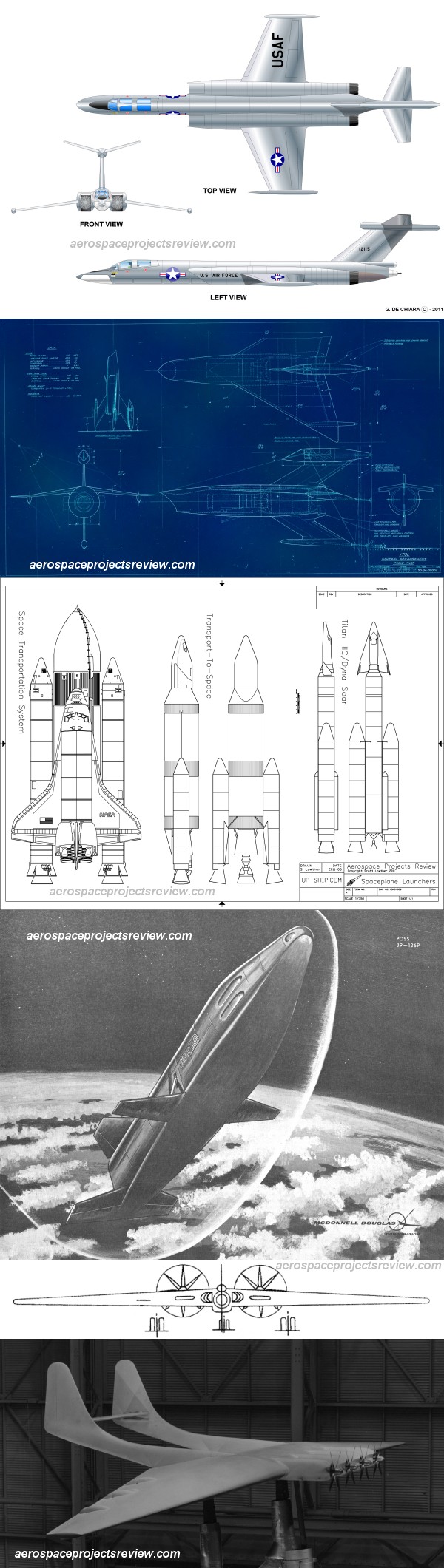
Likely either a Boeing or Martin Co. promotional/presentation image illustrating the “hypersonic research vehicle” phase/stage of the Dyna-Soar program, the first of three such phases/stages. The second as a “manned reconnaissance vehicle” and the third/final as a “full-fledged manned, hypersonic, global, strategic bombardment and reconnaissance system”.

Although I’m sure it’s due to the perspective view, the vehicle looks to be just a bit stretched. The bloppy stars & random brush strokes within the infinite void are likely a clue as to artist, but I'll be damned if I have it in me to pursue further.
8.5” x 11”.

The content of the following is uncomfortably prophetic when considering current disconcerting (to put it mildly) reality. I don’t want my children required to learn Mandarin. Speaking of which, Artemis crews should probably start learning some basic dialog, like requesting lunar orbit insertion clearance, submitting orbital track approvals, and of course, eventually, maybe...requesting permission to land. Maybe/hopefully they already have, I’ve heard it’s a difficult language:

“The proposed project would develop a manned, winged vehicle that would be rocket-boosted to hypersonic speed at an altitude above 30 km. It would then glide from 10,200 to 40,800 km, depending on the mission. The project was to be completed in three phases:

Dyna-Soar I would be a hypersonic research vehicle, boosted to 100 km altitude and 5.5 km/sec in its first version. This velocity would be increased later in the test program by the addition of a second stage. Range on test flights would be between 1800 and 5500 km. The booster could be powered by two of the high-performance liquid fluorine/hydrazine Chariot motors being developed by Bell. If these were not available in time, alternates would be a single Atlas sustainer engine or the X-15 XLR-99. Air-drop flights of the Dyna-Soar I were expected in March 1963, followed by single-stage booster flights a year later, and two-stage near-orbital booster flights by the end of 1965. This phase would replace the Hywards project and be accomplished in collaboration with NACA.

Dyna-Soar II would be a manned hypersonic reconnaissance vehicle, in replacement of the Brass Bell. This would use production versions of the Phase I hardware to boost the glider to 52 km altitude and 5.5 km/sec. From there it would glide at hypersonic speed over a range of 10,200 km. The pilot would monitor the operation of automated reconnaissance systems, which would consist of a high resolution camera, a side-looking radar, and 'ferret' (ELINT) sensors. Operation of these sensors at high speeds and under conditions of high airframe heating were considered to be a major development issue. The booster was expected to be powered by an Atlas sustainer engine, although use of the Chariot booster was a possibility if it could be developed in time. Dyna-Soar II would begin drop tests in January 1966, followed by boosted tests by the end of 1967. An operational weapons system was to be deployed in mid-1969. This would allow it to replace A-12 reconnaissance planes expected to be vulnerable by that time. If needed, Dyna-Soar II could be equipped with an interim nuclear weapons delivery capability if advances in Soviet development of anti-ballistic missile systems warranted that.

Dyna-Soar III would be a full-fledged manned, hypersonic, global, strategic bombardment and reconnaissance system. It would fulfill the Robo requirement, and require a multi-stage launch vehicle to take it to near-orbital velocity (7.6 km/sec) at 90 km altitude. Temperature loads were expected to be no greater than that for Dyna-Soar II, but the cooling system would be required to operate for a much longer period. A significant technical problem was expected to be achieving he desired 900 m CEP weapons delivery accuracy. First glide flight was expected in January 1970, followed by the first all-up boosted spaceflight in mid-1971. The Dyna-Soar III global weapon system would become operational in mid-1974.

The arguments for the weapon system were quite similar to those aired 45 years later. The Air Force was concerned that by the 1970's the ballistic missile would not be able to strike hardened targets with the necessary accuracy. They certainly couldn't hit mobile targets. Boost-glide was a more attractive alternative than air-breathing advanced turbojet or ramjet engines as a B-70 bomber follow-on. A rocket-propelled glider could fly at the entire speed range from Mach 5 to Mach 25 as required by the mission. Air-breathing systems would be much more complex, more difficult to develop, and only operate at lower speeds. Rand Corporation studies indicated anything below Mach 9 could be vulnerable to Soviet air defenses by 1965.

The Dyna-Soar could attack enemy targets from any direction. At its low approach altitude enemy radar systems would only provide three minutes warning of the attack, as opposed to twenty minutes for an ICBM. Unlike a ballistic missile, it could be recalled or retargeted during the mission. On the reconnaissance mission, it could glide over enemy targets between 45 and 90 km altitude, providing better resolution than orbiting satellites at much higher altitudes. The data would be available for analysis within hours of the overflight, compared to having to wait for days for recovery of the capsules from spy satellites. The enemy would also have no warning to conceal its activities, unlike a satellite in its predictable orbit.”

The above paraphrasing & extract are from/at the always wonderfully informative Astronautix website:

www.astronautix.com/d/dynasoar.html

As expected, websites pertaining to the X-20/Dyna-Soar are in abundance.

a07_v_bw_o_n (NAR publicity photo, WRC071568, A-168, S-68-41156 eq) by Mike Acs

© Mike Acs, all rights reserved.

a07_v_bw_o_n (NAR publicity photo, WRC071568, A-168, S-68-41156 eq)

“APOLLO 7 COMES HOME—Silver-colored Apollo spacecraft command module enters atmosphere near the conclusion of the 11-day manned mission in this artist’s drawing by North American Rockwell Corporation’s Space Division. In the first manned Apollo flight later this year, the crew members are (left to right) Walter M. Schirra Jr., commander; Walter Cunningham, command module pilot, and Donn Eisele, lunar module pilot. The Space Division produces the Apollo spacecraft command and service modules for NASA’s Manned Spacecraft Center.”

Possibly by the hand of Henry Lozano Jr.?

Note the similarity to Davis Meltzer's depiction for National Geographic magazine:

static.nationalgeographic.co.uk/files/styles/image_1190/p...
Credit: National Geographic UK website

STSprog_v_c_o_AKP (McDonnell Douglas Corp photo POSS 39-1269, D4C-68342, DEC 4 1969) by Mike Acs

© Mike Acs, all rights reserved.

STSprog_v_c_o_AKP (McDonnell Douglas Corp photo POSS 39-1269,  D4C-68342, DEC 4 1969)

Artist's concept of McDonnell Douglas Corporation's proposed “drawbridge wing” shuttle orbiter from late 1969...possibly right before breaking up, flipping over, disintegrating, or something like that...due to what looks to be an implausible angle-of-attack, to me at least.

8.5" x 11". A very dramatic & dynamic perspective...by H. Wynn.

Interesting reading:

www.pmview.com/spaceodysseytwo/spacelvs/sld024.htm
Credit: PMView website

myspacemuseum.blogspot.com/2012/06/early-space-shuttle-co...
Credit: My Space Museum website

The photograph, amongst others:

www.aerospaceprojectsreview.com/blog/wp-content/uploads/2...
Credit: Aerospace Projects Review (awesome) website

I had no idea there were this many designs/proposals & variations, holy cow:

io9.gizmodo.com/early-design-specs-show-the-space-shuttle...
Credit: Gizmodo website

a_v_c_o_AKP (unnumbered, S-63-14199 eq) by Mike Acs

© Mike Acs, all rights reserved.

a_v_c_o_AKP (unnumbered, S-63-14199 eq)

Artist's depiction of the Command Module's atmospheric re-entry.